Chapter
Page
Table of Contents
Using the Meter
Miscellaneous
TOC-4
Highlights
Introduction
Description
EPM 6000 Highlights
Features
Universal Voltage Inputs
Current Inputs
Utility Peak Demand
Measured Values
EPM 6000 Measured Values
EPM 6000 Order Codes
Ordering
Order Codes
Metering
Specifications
Inputs/Outputs
Mechanical Parameters
Environmental
Communications
Type Testing
Approvals
Three-Phase Power Measurement
Three-Phase System Configurations
Wye Connection
Common Phase Voltages on Wye Services
Vcn
Three-Phase Delta Winding Relationship
Delta Connection
Blondells Theorem and Three-Phase Measurement
Three-Phase, Four-Wire Delta Phasors
Phase B Phase C Node n Phase a
Electrical Background
Energy
Power, Energy, and Demand
Power
Power Use Over Time
Power and Energy Relationship Over Time
Demand
Energy Use and Demand Intervals
Reactive Energy and Power Factor
Real, Reactive, and Apparent Power
Power Factor
Apparent power
Harmonic Distortion
Harmonics of a Non-Sinusoidal Waveform
Inductive and Capacitive Impedance
Voltage and Current Monitoring
Waveform Capture
Power Quality
Typical Power Quality Problems
Electrical Background
Mechanical Installation
Dimensions
Ansi Installation Steps
Ansi and DIN Mounting Panel Cutouts
DIN Installation Steps
Ansi Mounting Procedure
DIN Mounting Procedure
Electrical Installation
Installation Considerations
CT Leads Terminated to Meter
CT Leads Pass-Through No Meter Termination
Voltage and Power Supply Connections
Quick Connect Crimp CT Terminations
Ground Connections
Voltage Connection
Wiring Diagrams
2 Wye, 4-Wire with no PTs and 3 CTs, 3 Element
4-Wire Wye with no PTs and 3 CTs, 3 Element
3 Wye, 4-Wire with no PTs and 3 CTs, 2.5 Element
10 4-Wire Wye with no PTs and 3 CTs, 2.5 Element
4 Wye, 4-Wire with 3 PTs and 3 CTs, 3 Element
11 4-Wire Wye with 3 PTs and 3 CTs, 3 Element
5 Wye, 4-Wire with 2 PTs and 3 CTs, 2.5 Element
12 4-Wire Wye with 2 PTs and 3 CTs, 2.5 Element
Delta, 3-Wire with no PTs and 2 CTs
13 3-Wire Delta with no PTs and 2 CTs
Delta, 3-Wire with 2 PTs and 2 CTs
14 3-Wire Delta with 2 PTs and 2 CTs
Current-Only Measurement Three-Phase
Current-Only Measurement Dual-Phase
Current-Only Measurement Single-Phase
3 RS485 COM2 Port
Communications Setup
IrDA COM1 Port
16 RS485 Communications Installation
Front Panel Interface
Faceplate Elements
Using the Meter
Faceplate Buttons
Percentage of Load Bar
% of Load Bar Segments
Watt-Hour Accuracy Testing Verification
EPM 6000 Accuracy Test Constants
Start Up
Configuring the Meter via the Front Panel
Overview
Reset Mode and Password Entry
Main Menu
Using the Meter
Using the Meter
Changing Settings in Configuration Mode
Configuring the Scroll Feature
Programming the Configuration Mode Screens
Configuring the CT Setting
Configuring the PT Setting
Value for amps is a product of the Ct-nand the Ct-Svalues
Configuring the Connection Setting
Configuring the Communication Port Setting
Address
Using the Meter
Operating Mode
Operating Mode Parameter Readings
Using the Meter
Memory Map
Modbus Communications
Memory Map Description
HEX
Range Units or Comments
THD Block7
Description 1 Format Range
7532 PT denominator
Modbus Memory Map Notes
Secondary Readings Section
Communications
Modbus Memory Map Data Formats
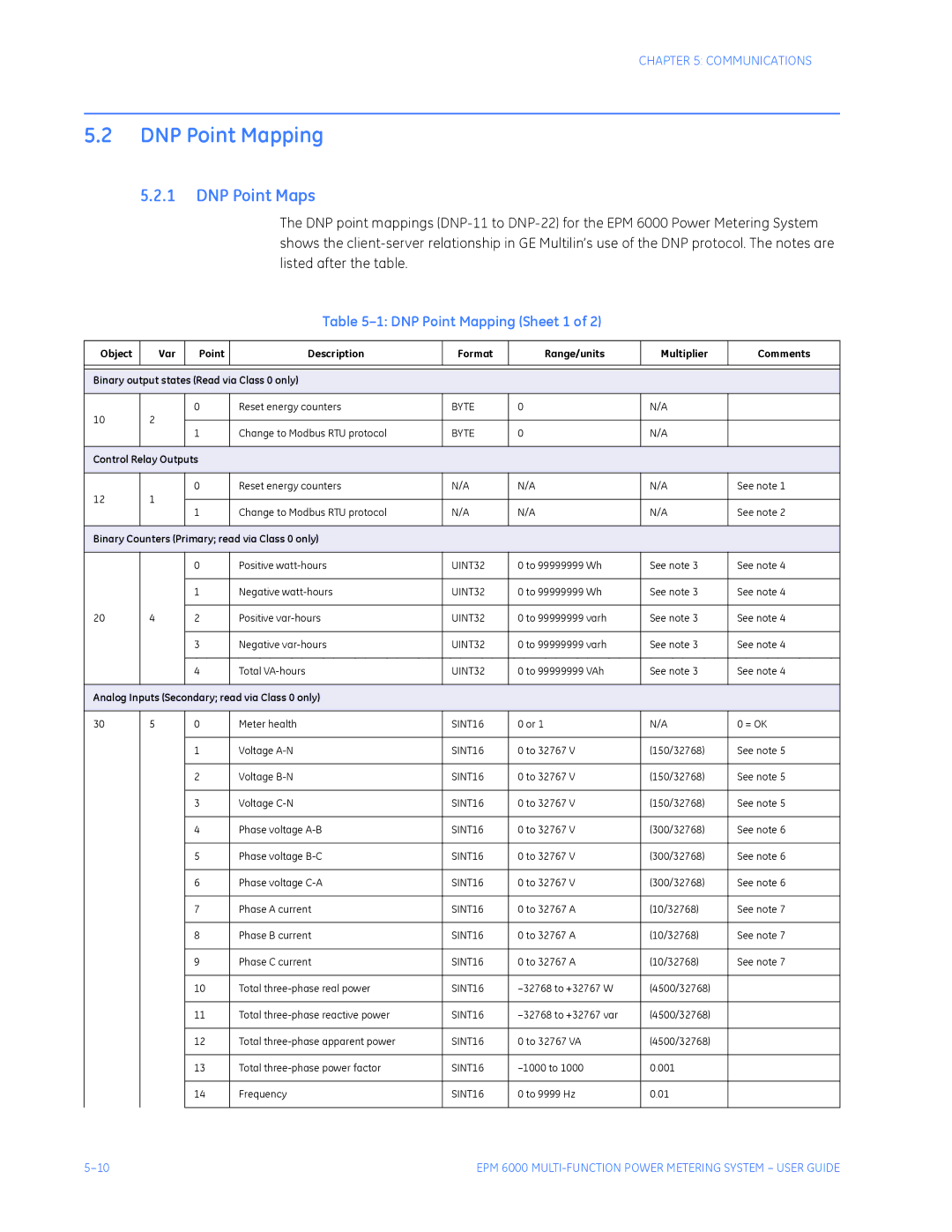
DNP Point Mapping Sheet 1
DNP Point Mapping
DNP Point Maps
DNP Point Mapping Sheet 2
DNP Point Map Notes
Transport Layer
DNP Implementation
Data Link Layer
Application Layer
Following function codes are implemented on the EPM
Control Relay Output Object 12, Variation
DNP Objects and Variations
Binary Output Status Object 10, Variation
4 32-Bit Binary Counter Without Flag Object 20, Variation
5 16-Bit Analog Input Without Flag Object 30, Variation
Class 0 Data Object 60, Variation
Internal Indications Object 80, Variation
Communications
Navigation Maps
Introduction
Main Menu Screens
Main Menu Navigation
Operating Mode Screens
Operating Mode Navigation
Reset Mode Screens
Reset Mode Navigation
Configuration Mode Screens
Changes to the Manual
Revision History
Release Dates
Major Updates for 1601-0215-A2
Warranty
GE Multilin Warranty
Index
Irda
Power Supply
Wiring
