PR70e
Important Safety Instructions
Contents
Related Manuals
Models
Electric Shock Hazard
Fire and Explosion Hazard
Machine
Component Identification
IG Machine Key
AB System Shut-Down Key
Local Control Module LCM
LCM Screen Navigation
Screen Overview and Appendix C LCM Setup
Run Screen
Component Identification 334135B
Dispense Valve
Recommended Parts
Standard Dispense Valves, 255179
Gun Mounted MD2 Valves, LC0120 and LC0122
Part Description Quantity
Lever Actuated MD2 Valves, LC0121 and LC0123
Mixers
1301 1302 1303 Mixer
Reference Number and Description
Shroud
Package Description
Part Description Mounting, valve, HMI Mounting, HMI
Applicator Mounting
Air Filter and Ball Valve, 24R707
High Temperature Grease Footswitch
Tanks
Quantity Part Description 24W415 24W416 24W417
Unheated, Non-Recirculating Hose
Hose Packages
Recommended Parts 334135B
Nylon Piston, Stainless Steel Metering Tube Assemblies
Piston Package
Uhmw
Uhmw Piston, Stainless Steel Metering Tube Assemblies
Shot Size cc Air Motor In. Air Motor
Pump Tube Combination Information
Machine Installation
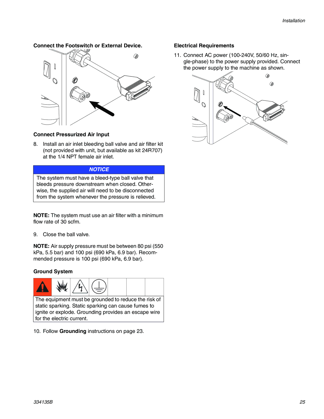
Installation
Grounding
General Grounding Guidelines
Install the Dispense Valve and Support Arm, if needed
Install the Chemical Hoses
Electrical Requirements
Ground System
Piston Position Calibration
Setup
Navigate to the Shot Mode Screen or Operator Mode Screen
Perform Pressure Relief Procedure on
Engaged Piston Position
Manually Move the Piston Drive Block
Prime Dispense Head
Prime the Dispense Head
Adjust Dispense Quantity
Phasing Adjustment
Prepare the Machine
Navigate to the Phasing Shot Calibration Screen
Adjust Phasing
Adjust Dispense Valve Snuff Back
Operator Mode Screen
Adjust Open Dispense Valve ODV Timing
Navigate to the Maintenance Mode Run Screen
Pressure Relief Procedure
Operation
Startup
Shutdown
Relieve pressure. See Pressure Relief Procedure,
Clean the Pump Shafts
Maintenance
Disassemble and Clean the Dispense Head
Schedule
Remove Access Panel
Install Upgrade Token
Problem Cause Solution
Troubleshooting
Problem Cause Solution
Trigger
LCM Error Codes
Code Name Type Causes Fixes Condition
Entries in Position Calibra
Prepare Machine for Kit Installation
HydraCheck Kit Installation, 24W336
Repair
Adjust the Adjustment Screw/Cap
Install Adjustment Screw/Cap
Adjust Shock Resistance
Disassemble the Air Cylinder
Air Cylinder Rebuild Instructions
Re-Assemble the Air Cylinder
Clean and Inspect the Parts
Rear Pump Rebuild Instructions
Prepare for Operation
Assemble the Rear Pump Assembly
Install Cylinder
Piston/Cylinder Replacement Kit Installation
Disassemble Cylinder
Check Valve Rebuild Kit Installation
Fixed Ratio Base
Parts
24V935, Pump 24V936, Pump Part Description Assembly
Pump Sub-Assembly, 24S053
Collar
Check Valve, Assembly LC0093
206 201 204 205 202 203
Fixed Ratio Drive Block Assembly, LC0107
24V933, Motor 24V934, Motor Part Description Air
Air Cylinder, 24V933
Fixed Ratio Frame Sub-Assembly, LC0290
Ring, support Carbide Package Pump Piston Washer Screw Ball
Uhmw Piston, Ceramic Metering Tube Assemblies
Electrical Schematics
Schematics
Electrical Schematic
DB25 Pin Function
Pneumatic Schematic
DB25 Pin Number Pin Function Description
Schematics 334135B
Appendix a LCM Icon Overview
Position Adjust
Phasing Shot Adjust
Adjust
Amount Adjust
Disable Mode Screen
Splash Screen Operator Mode Screen
Shot Mode Screen
Mode Selection Programming Screen
Shot Amount or Stroke % Adjust Screen
Maintenance Mode Run Screen
Error Code Acknowledgement Screen
Run Screen while Dispensing
Setup Screen Password Set/Clear Screen
Appendix C LCM Setup Screen Overview
Phasing Shot Calibration Screen
Kits
Nylon and Uhmw Piston Replacement Kits
LCF Piston Size mm2
LCE Piston Size mm2
MD2 Valve
Recommended Spare Parts
Dimensions
Dimensions
Technical Data
Graco Information
Graco Standard Warranty