Setup
Setup
Before setting up the machine, the user needs to be familiar with the LCM screens. Refer to Appendix A - LCM Icon Overview and Appendix B - LCM Run Screen Overview, starting on page 60.
Perform Startup, page 33, to access the LCM screens.
Piston Position Calibration
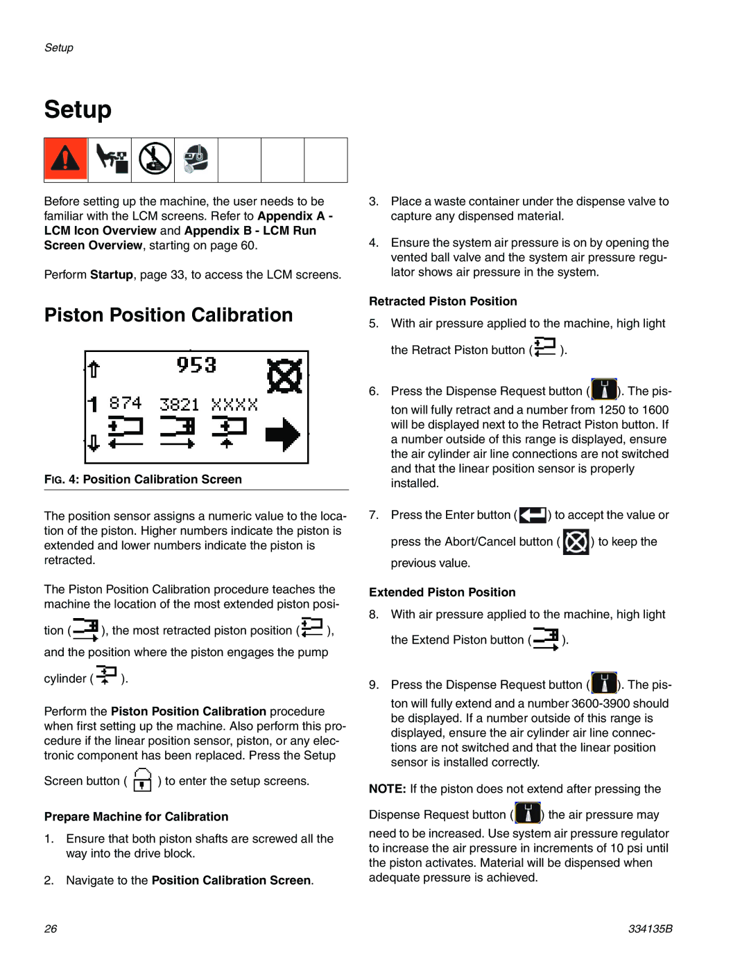
FIG. 4: Position Calibration Screen
The position sensor assigns a numeric value to the loca- tion of the piston. Higher numbers indicate the piston is extended and lower numbers indicate the piston is retracted.
The Piston Position Calibration procedure teaches the machine the location of the most extended piston posi-
tion (![]() ), the most retracted piston position (
), the most retracted piston position (![]() ), and the position where the piston engages the pump
), and the position where the piston engages the pump
cylinder (![]() ).
).
Perform the Piston Position Calibration procedure when first setting up the machine. Also perform this pro- cedure if the linear position sensor, piston, or any elec- tronic component has been replaced. Press the Setup
Screen button ( ![]() ) to enter the setup screens.
) to enter the setup screens.
Prepare Machine for Calibration
1.Ensure that both piston shafts are screwed all the way into the drive block.
2.Navigate to the Position Calibration Screen.
3.Place a waste container under the dispense valve to capture any dispensed material.
4.Ensure the system air pressure is on by opening the vented ball valve and the system air pressure regu- lator shows air pressure in the system.
Retracted Piston Position
5.With air pressure applied to the machine, high light
the Retract Piston button (![]() ).
).
6.Press the Dispense Request button ( ![]() ). The pis- ton will fully retract and a number from 1250 to 1600 will be displayed next to the Retract Piston button. If a number outside of this range is displayed, ensure the air cylinder air line connections are not switched and that the linear position sensor is properly installed.
). The pis- ton will fully retract and a number from 1250 to 1600 will be displayed next to the Retract Piston button. If a number outside of this range is displayed, ensure the air cylinder air line connections are not switched and that the linear position sensor is properly installed.
7.Press the Enter button ( ![]() ) to accept the value or
) to accept the value or
press the Abort/Cancel button ( ![]() ) to keep the previous value.
) to keep the previous value.
Extended Piston Position
8.With air pressure applied to the machine, high light
the Extend Piston button (![]() ).
).
9.Press the Dispense Request button ( ![]() ). The pis- ton will fully extend and a number
). The pis- ton will fully extend and a number
NOTE: If the piston does not extend after pressing the
Dispense Request button ( ![]() ) the air pressure may
) the air pressure may
need to be increased. Use system air pressure regulator to increase the air pressure in increments of 10 psi until the piston activates. Material will be dispensed when adequate pressure is achieved.
26 | 334135B |