Gun Overview
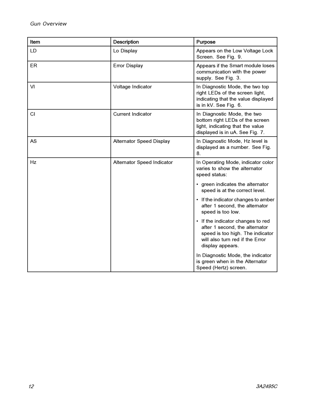
Item | Description | Purpose |
|
|
|
LD | Lo Display | Appears on the Low Voltage Lock |
|
| Screen. See Fig. 9. |
ER | Error Display | Appears if the Smart module loses |
|
| communication with the power |
|
| supply. See Fig. 3. |
VI | Voltage Indicator | In Diagnostic Mode, the two top |
|
| right LEDs of the screen light, |
|
| indicating that the value displayed |
|
| is in kV. See Fig. 6. |
CI | Current Indicator | In Diagnostic Mode, the two |
|
| bottom right LEDs of the screen |
|
| light, indicating that the value |
|
| displayed is in uA. See Fig. 7. |
AS | Alternator Speed Display | In Diagnostic Mode, Hz level is |
|
| displayed as a number. See Fig. |
|
| 8. |
Hz | Alternator Speed Indicator | In Operating Mode, indicator color |
|
| varies to show the alternator |
|
| speed status: |
|
| • green indicates the alternator |
|
| speed is at the correct level. |
|
| • If the indicator changes to amber |
|
| after 1 second, the alternator |
|
| speed is too low. |
|
| • If the indicator changes to red |
|
| after 1 second, the alternator |
|
| speed is too high. The indicator |
|
| will also turn red if the Error |
|
| display appears. |
|
| In Diagnostic Mode, the indicator |
|
| is green when in the Alternator |
|
| Speed (Hertz) screen. |
12 | 3A2495C |