Gun Setup
19.Check that the ES indicator (K) [Hz indicator on Smart guns] is lit. See the following table.
Table 2 . LED Indicator Colors
Indicator | Description |
Color |
|
|
|
Green | When spraying, the indicator |
| should remain green, indicating |
| sufficient air pressure to the |
| alternator turbine. |
Amber | If the indicator changes to amber |
| after 1 second, the air pressure |
| is too low. Increase air pressure |
| until the indicator is green. |
Red | If the indicator changes to red |
| after 1 second, the air pressure is |
| too high. Decrease air pressure |
| until the indicator is green. |
20.Set the gun air regulator to deliver a minimum of 45 psi (0.32 MPa, 3.2 bar) at the gun when triggered, to ensure full spraying voltage. See the table below.
Table 3 . Pressure Drop
Air | Hose | Air Regulator Setting | |
Length in ft (m) | in psi (MPa, bar) | ||
(using 5/16 in. [8 | [with gun triggered] | ||
mm] diameter hose) |
|
| |
15 | (4.6) | 52 | (0.36, 3.6) |
25 | (7.6) | 57 | (0.40, 4.0) |
50 | (15.3) | 68 | (0.47, 4.7) |
75 | (22.9) | 80 | (0.56, 5.6) |
|
|
|
|
100 | (30.5) | 90 | (0.63, 6.3) |
|
|
|
|
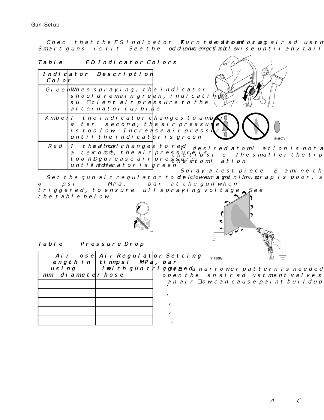
21.Turn the atomizing air adjustment valve counterclockwise until any tails disappear.
22.If desired atomization is not achieved, change the tip size. The smaller the tip orifice, the finer the atomization.
23.Spray a test piece. Examine the edges for coverage. If wrap is poor, see Troubleshooting, page 35.
NOTE: If a narrower pattern is needed occasionally, open the fan air adjustment valve slightly. (Excessive fan air flow can cause paint buildup on the air cap.)
20 | 3A2495C |
