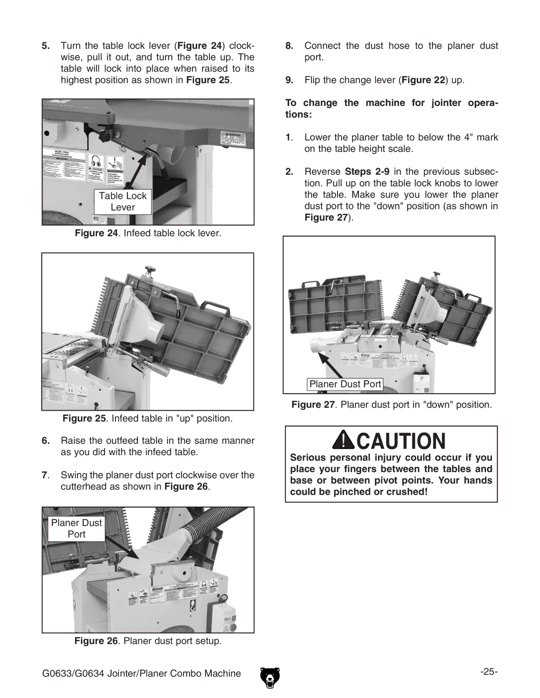
5.Turn the table lock lever (Figure 24) clock- wise, pull it out, and turn the table up. The table will lock into place when raised to its highest position as shown in Figure 25.
Table Lock
Lever
Figure 24. Infeed table lock lever.
Figure 25. Infeed table in "up" position.
6.Raise the outfeed table in the same manner as you did with the infeed table.
7. Swing the planer dust port clockwise over the cutterhead as shown in Figure 26.
Planer Dust
Port
Figure 26. Planer dust port setup.
G0633/G0634 Jointer/Planer Combo Machine
8.Connect the dust hose to the planer dust port.
9.Flip the change lever (Figure 22) up.
To change the machine for jointer opera- tions:
1. Lower the planer table to below the 4" mark on the table height scale.
2.Reverse Steps
Planer Dust Port
Figure 27. Planer dust port in "down" position.
Serious personal injury could occur if you place your fingers between the tables and base or between pivot points. Your hands could be pinched or crushed!
