4.Using a 14mm wrench, loosen the four adjustment nuts and raise the motor (see Figure 47) to remove
Adjustment
Nuts
Figure 47. Removing V-belt tension.
5.Remove both the belts and replace them with a new set.
6.Lower the motor and reinstall the belt tension knob.
7.Using the belt tension knob, adjust the V- belt tension so there is approximately 1⁄4"–1⁄2" deflection when the V-belts are pushed with moderate pressure as shown in Figure 48.
Note: After the first 16 hours of belt life, retension the belts, as they will stretch and seat during this time.
������
����������
������
Figure 48. Checking V-belt tension.
G0633/G0634 Jointer/Planer Combo Machine
8.Replace the motor access cover, fence brack- et, and fence.
Lubrication
Since all bearings are sealed and permanently lubricated, simply leave them alone until they need to be replaced. DO NOT lubricate them.
Proper lubrication of other jointer/planer compo- nents is essential for long life and
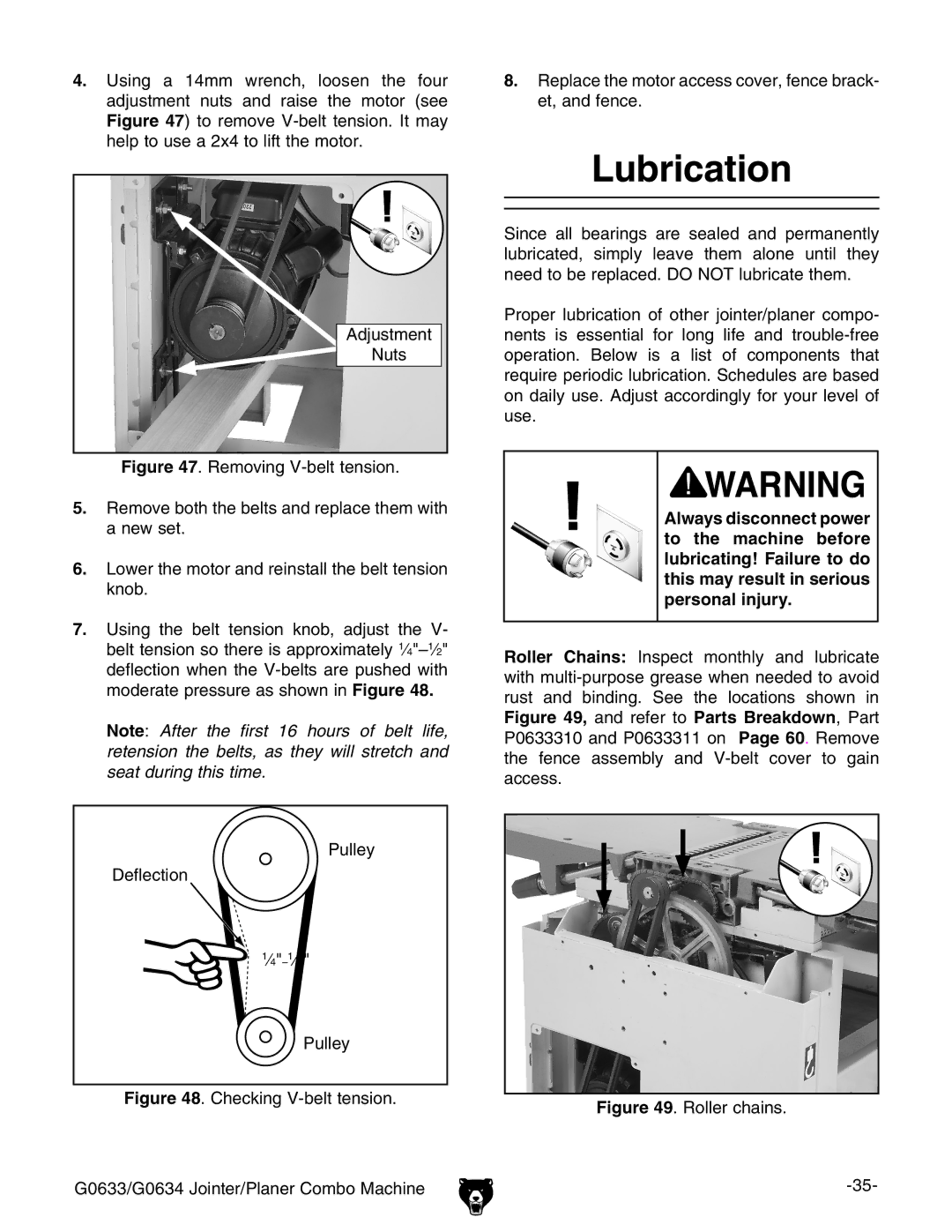
Always disconnect power to the machine before lubricating! Failure to do this may result in serious personal injury.
Roller Chains: Inspect monthly and lubricate with
