To adjust/replace the knives:
1.DISCONNECT THE JOINTER/PLANER FROM THE POWER SOURCE!
2.Remove the cutterhead guard from the table, and flip up the lower the infeed and outfeed tables. This will give you unrestricted access to the cutterhead.
3.Remove the motor access panel to expose the motor pulley.
4.Rotate the motor pulley to give you good access to one of the cutterhead knives.
Knives are sharp! When adjusting knives, wear gloves or cover knives with rags to avoid contact with knives, which could cause serious personal injury.
5.Loosen the cutterhead gib bolts, starting in the middle and alternating back and forth until all of the gib bolts are loose, but not falling out.
6.Remove and clean the gibs and clean inside the cutterhead slot to remove all pitch or saw- dust. Coat the knives and gibs with a metal protectant (Page 32), then fit the gibs back in the cutterhead with the new knives.
7.Adjusting the knife heights:
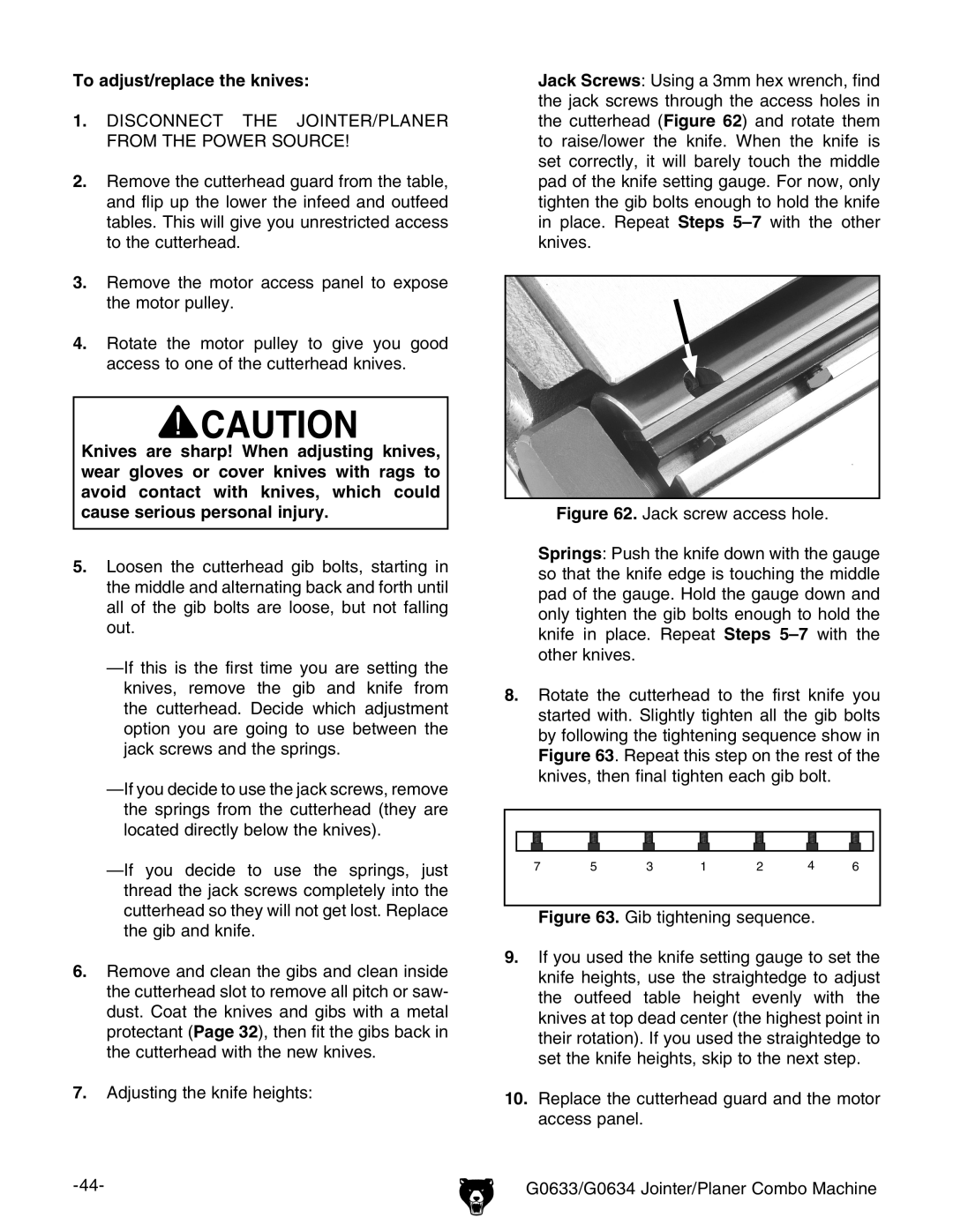
Jack Screws: Using a 3mm hex wrench, find the jack screws through the access holes in the cutterhead (Figure 62) and rotate them to raise/lower the knife. When the knife is set correctly, it will barely touch the middle pad of the knife setting gauge. For now, only tighten the gib bolts enough to hold the knife in place. Repeat Steps
Figure 62. Jack screw access hole.
Springs: Push the knife down with the gauge so that the knife edge is touching the middle pad of the gauge. Hold the gauge down and only tighten the gib bolts enough to hold the knife in place. Repeat Steps 5–7 with the other knives.
8.Rotate the cutterhead to the first knife you started with. Slightly tighten all the gib bolts by following the tightening sequence show in Figure 63. Repeat this step on the rest of the knives, then final tighten each gib bolt.
7 | 5 | 3 | 1 | 2 | 4 | 6 |