5.DISCONNECT MACHINE FROM POWER!
6.Remove the two outer die brackets, then both dies.
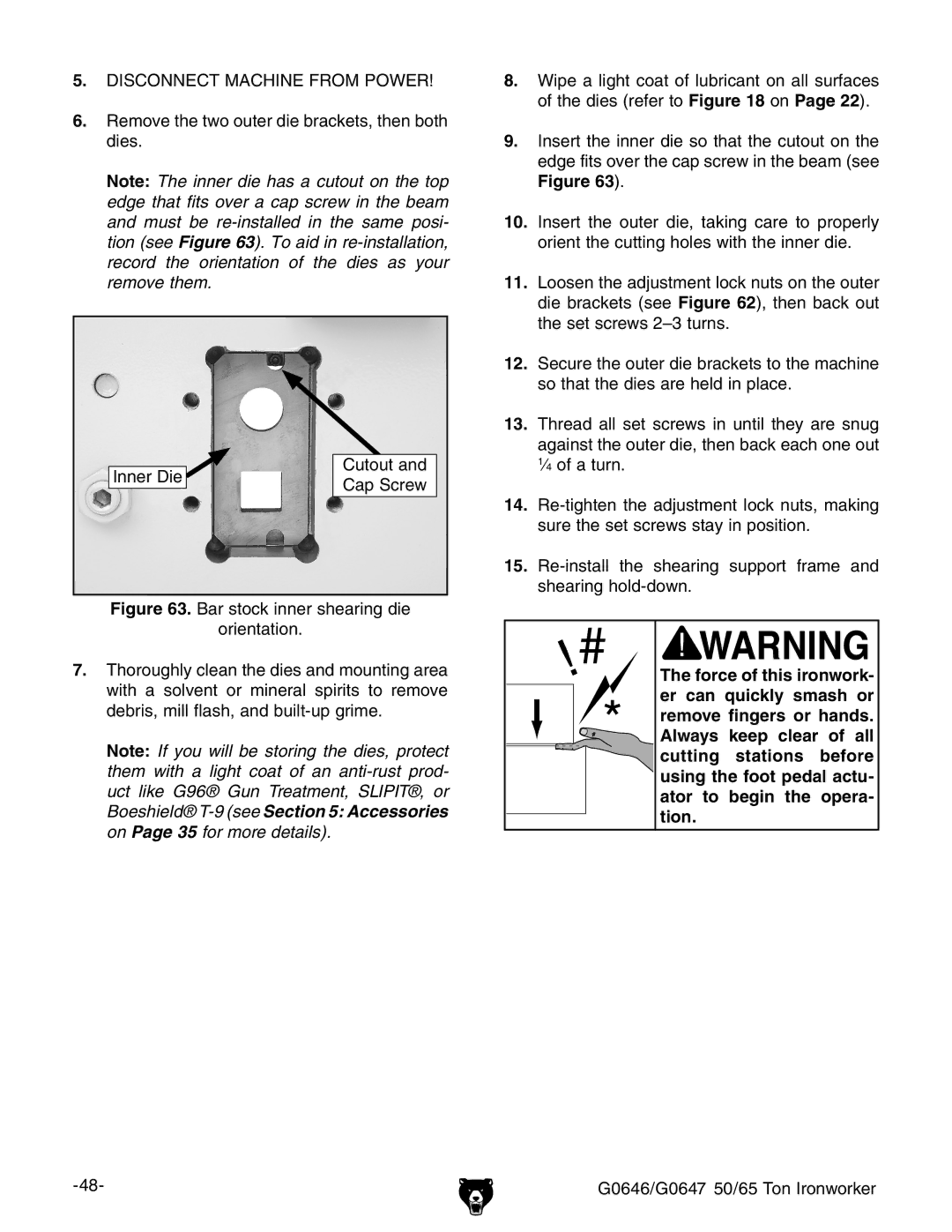
Note: The inner die has a cutout on the top edge that fits over a cap screw in the beam and must be
|
| Cutout and |
Inner Die |
| |
| Cap Screw | |
|
|
Figure 63. Bar stock inner shearing die
orientation.
7.Thoroughly clean the dies and mounting area with a solvent or mineral spirits to remove debris, mill flash, and built-up grime.
Note: If you will be storing the dies, protect them with a light coat of an
8.Wipe a light coat of lubricant on all surfaces of the dies (refer to Figure 18 on Page 22).
9.Insert the inner die so that the cutout on the edge fits over the cap screw in the beam (see Figure 63).
10.Insert the outer die, taking care to properly orient the cutting holes with the inner die.
11.Loosen the adjustment lock nuts on the outer die brackets (see Figure 62), then back out the set screws 2–3 turns.
12.Secure the outer die brackets to the machine so that the dies are held in place.
13.Thread all set screws in until they are snug against the outer die, then back each one out 1⁄4 of a turn.
14.Re-tighten the adjustment lock nuts, making sure the set screws stay in position.
15.Re-install the shearing support frame and shearing hold-down.
The force of this ironwork- er can quickly smash or remove fingers or hands. Always keep clear of all cutting stations before using the foot pedal actu- ator to begin the opera- tion.