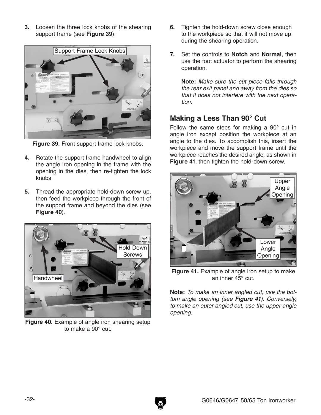
3.Loosen the three lock knobs of the shearing support frame (see Figure 39).
Support Frame Lock Knobs
Figure 39. Front support frame lock knobs.
4.Rotate the support frame handwheel to align the angle iron opening in the frame with the opening in the dies, then re-tighten the lock knobs.
5.Thread the appropriate hold-down screw up, then feed the workpiece through the front of the support frame and beyond the dies (see Figure 40).
Hold-Down
Screws
Handwheel
Figure 40. Example of angle iron shearing setup
to make a 90° cut.
6.Tighten the hold-down screw close enough to the workpiece so that it will not move up during the shearing operation.
7.Set the controls to Notch and Normal, then use the foot actuator to perform the shearing operation.
Note: Make sure the cut piece falls through the rear exit panel and away from the dies so that it does not interfere with the next opera- tion.
Making a Less Than 90° Cut
Follow the same steps for making a 90° cut in angle iron except position the workpiece at an angle to the dies. To accomplish this, insert the workpiece and move the support frame until the workpiece reaches the desired angle, as shown in Figure 41, then tighten the
Upper
Angle
Opening
Lower
Angle
Opening
Figure 41. Example of angle iron setup to make
an inner 45° cut.
Note: To make an inner angled cut, use the bot- tom angle opening (see Figure 41). Conversely, to make an outer angled cut, use the upper angle opening.