Identification
C
B![]()
A ![]()
D
E
F
G
H
I
Q
W
X
R | S |
|
T
![]()
![]() U
U
V
Figure 2.
K
J
P ![]()
Figure 3.
Front view identification. | |||
L |
|
|
|
|
|
| |
| M |
| |
|
|
| |
N
O
Rear view identification.
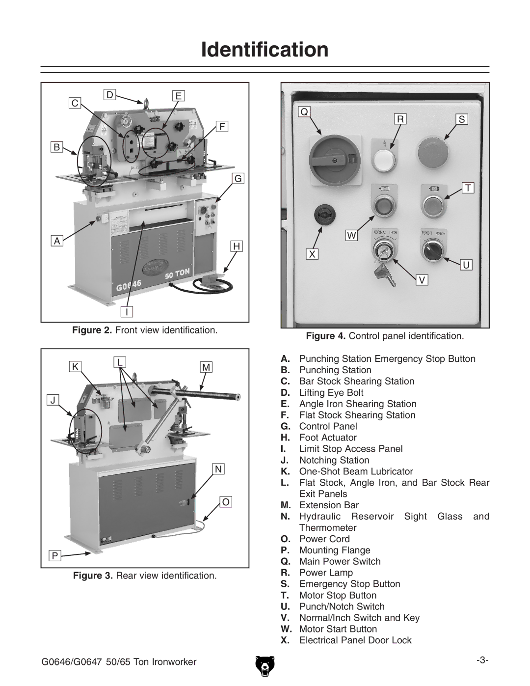
Figure 4. Control panel identification.
A.Punching Station Emergency Stop Button
B.Punching Station
C.Bar Stock Shearing Station
D.Lifting Eye Bolt
E.Angle Iron Shearing Station
F.Flat Stock Shearing Station
G.Control Panel
H.Foot Actuator
I.Limit Stop Access Panel
J.Notching Station
K.One-Shot Beam Lubricator
L.Flat Stock, Angle Iron, and Bar Stock Rear Exit Panels
M.Extension Bar
N.Hydraulic Reservoir Sight Glass and Thermometer
O.Power Cord
P.Mounting Flange
Q.Main Power Switch
R.Power Lamp
S.Emergency Stop Button