RS–232
5700–X1, 5700–X2 (TTL) and 5700–X3 (True)
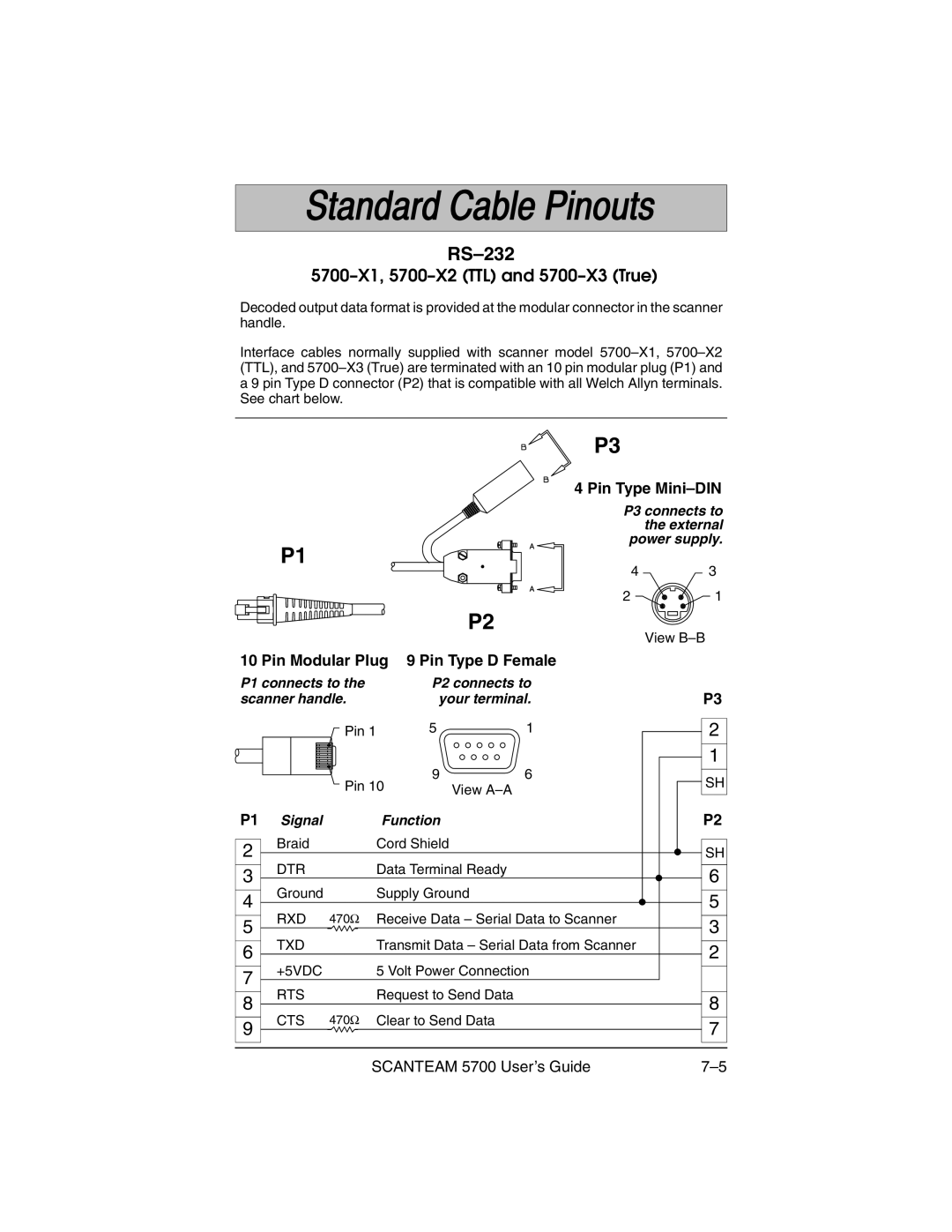
Decoded output data format is provided at the modular connector in the scanner handle.
Interface cables normally supplied with scanner model
P3
4 Pin Type
P3 connects to the external power supply.
P1
4 3
21
P2
View
10 Pin Modular Plug 9 Pin Type D Female
P1 connects to the | P2 connects to | ||||
scanner handle. | your terminal. | ||||
|
| Pin 1 | 5 | 1 | |
|
|
| 9 | 6 | |
|
| Pin 10 | View | ||
P1 Signal |
| Function |
| ||
2 | Braid |
| Cord Shield |
| |
|
|
|
| ||
3 | DTR |
| Data Terminal Ready | ||
Ground |
| Supply Ground | |||
4 |
| ||||
RXD | 470Ω | Receive Data – Serial Data to Scanner | |||
5 | |||||
TXD |
| Transmit Data – Serial Data from Scanner | |||
6 |
| ||||
+5VDC |
| 5 Volt Power Connection | |||
7 |
| ||||
RTS |
| Request to Send Data | |||
8 |
| ||||
CTS | 470Ω | Clear to Send Data | |||
9 | |||||
|
|
|
| ||
P3
2
1
SH
P2
SH
6
5
3
2
8
7
SCANTEAM 5700 User’s Guide |