Models
What to do if you smell gas
Do Discardnot
HOT Surfaces
Congratulations
Homeowner Reference Information
Table of Contents
User Guide
Reference Materials
Appliance Setup
Troubleshooting
Limited Lifetime Warranty
Limited Lifetime Warranty
Warranty Conditions
Listing and Code Approvals
Installation of Carbon Monoxide Detectors
Requirements for the Commonwealth of Massachusetts
Your Fireplace
Gas Fireplace Safety
Operating Instructions User Guide
Fixed Glass Assembly
Remote Controls, Wall Controls and Wall Switches
IPI Battery Tray/Battery Installation
Clear Space
Module Reset
Nine Hour Safety Shutdown Feature
Control Module Operation
Before Lighting Fireplace
Lighting Instructions IPI
Final inspection by
What to do if YOU Smell GAS
GAS Valve
After Fireplace is Lit
Frequently Asked Questions
Issue Solutions
Maintenance and Service
Maintenance Tasks-Homeowner
Glass Cleaning Exterior of Installed Glass Only
Remote Control Optional
Maintenance Tasks-Qualified Service Technician
Glass Cleaning Exterior and Interior of Installed Glass
Gasket Seal and Glass Assembly Inspection
Logs
Burner Ignition and Operation
IPI Pilot Flame Patterns
Getting Started
Typical Appliance System
Inspect Appliance and Components
Design and Installation Considerations
Tools and Supplies Needed
Framing and Clearances
Selecting Appliance Location
HEIR36
HEIR42
Clearances
Minimum Framing Dimensions
Constructing the Appliance Chase
Mantel and Wall Projections
Non-Combustible Zone
Combustible Mantel Legs or Wall Projections
Non-Combustible Mantel Legs or Wall Projections
NON-COMBUSTIBLE Material HEIR50 Fireplace Opening
Combustible Mantel Allowance HEIR36, HEIR42
Hearth Extension
Model
Termination Locations
Vent Termination Minimum Clearances
Clearance above electrical service
Covered Alcove Applications
Vent Information and Diagrams
HEIR36 NG/LP, HEIR42 NG/LP HEIR50 NG/LP
Top Vent Horizontal Termination
One Elbow
Two Elbows
H1+ H2
Top Vent Horizontal Termination Three Elbows
HEIR36 NG/LP, HEIR42 NG/LP, HEIR50 NG/LP
Flue Restrictor
Top Vent Vertical Termination
Elbows
Top Vent Vertical Termination Three Elbows
Ht Max
PVK-80 and PVI-SLP Information
PVI-SLP
HEIR36
HEIR42
Vent Clearances and Framing
Pipe Clearances to Combustibles
Wall Penetration Framing
Non-Combustible Wall Penetration
Install the Ceiling Firestop
Pipe DVP
Install Attic Insulation Shield
Installing the Optional Heat-ZoneGas Kit
Flat Ceiling Installation
Vaulted Ceiling Installation
Appliance Preparation
Vent Preparation
Securing and Leveling the Appliance
Side Nailing Tab in Shipping Position
Installing Non-combustible Facing Material
Installing Non-Combustible Facing Material
Installing Vent Pipe DVP Pipe
Attach Vent to the Firebox Assembly
Assemble Vent Sections
Assemble Pipe Sections
Secure the Vent Sections
Disassemble Vent Sections
Install Metal Roof Flashing
Assemble and Install Storm Collar
Heat Shield Requirements for Horizontal Termination
Install Vertical Termination Cap
Install Horizontal Termination Cap
Gas Information
Fuel Conversion
Gas Pressure
Gas Connection
Wiring Requirements
IntelliFire PlusTM Ignition System Wiring
Optional Accessories Requirements
Electrical Information
Electrical Service and Repair Junction Box Installation
Access Through Left Column Access Through Firebox
Finishing Templates
Template installation instruction
Finishing
Splatter Guard
Finishing Template Bends Inoperable Fixed Doors
Non-Combustible Zone
Combustible Mantel Projections
10 Combustible Mantel Allowance HEIR36, HEIR42
Facing Material
Model HEIR36
Dimension Inoperable Operable Door
Doors
Arch
Operable Doors
Appliance Setup
Install the Log Assembly Log Set Assembly LOGS-HEIR36
LOG Placement Tabs LOG Placement Slot Notch for
Models HEIR36H, HEIR36S
LOG#4
Burner Grate Notch
LOG Contacts Notch Rests On Burner Grate Tine HEIR42 only
Burned Edge Portion
Contacts Back
Burned Portion Edge of LOG Used For Positioning For LOG #5
Burned Portion
LOG does not 2CONTACT Grate Tine
HEIR42 Shown
Log Set Assembly LOGS-HEIR50 Models HEIR50T, HEIR50H
LOG Contacts Grate Tine
Burned Edge LOG Contacts Side Refractory
LOG Contacts Grate Tine Approximately
HEIR36 HEIR42 HEIR50
TOP Retaining Rail Notch Glass Frame Notch
Air Shutter Setting
Air Shutter Settings
Flame Appearance
Full Open
IntelliFire Plus Ignition System
Troubleshooting
Symptom Possible Cause Corrective Action
Troubleshooting
Appliance Dimension Diagram
Reference Materials
1905
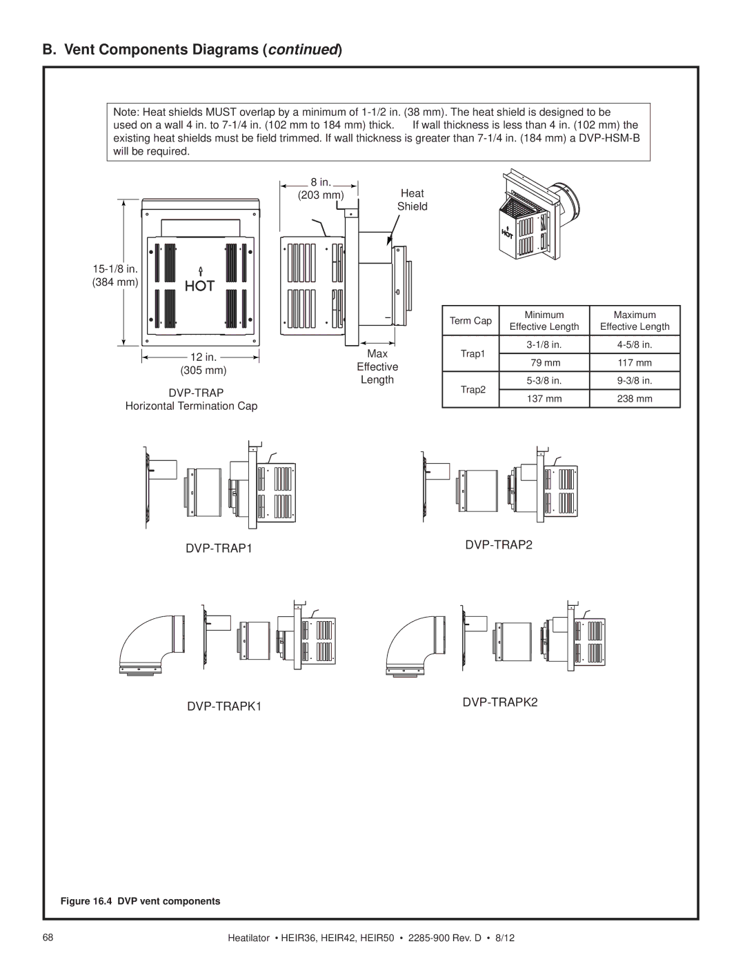
Vent Components Diagrams
DVP-AS2
DVP-TRAP1 DVP-TRAP2 DVP-TRAPK1 DVP-TRAPK2
DVP-TRAP
RF6M RF12M
BEK DVP-BEK2
DVP-TRAPFL
COOL-ADD
SLP-LPC
Optional Wire Harness
Description Part Number
Service Parts
Log Set Assembly
At Depot
Description Comments Part Number
Description Comments Part Number
#19 Traditional Refractory #20 Herringbone Refractory
Stocked
HEIR42T, HEIR42H
HEIR42T, HEIR42H
Log Set Assembly
HEIR50T, HEIR50H
#20 Traditional Refractory #21 Herringbone Refractory
#11 Valve Assembly
HEIR36, HEIR42, HEIR50
MYSTIC-EMBERS
Contact Information