Hitachi
Table of Contents
Xvi
Definitions and Symbols
Safety Messages
Hazardous High Voltage
General Precautions Read These First
Iii
Precautions for EMC Electromagnetic Compatibility
Installation Cautions for Mounting Procedures
Index to Warnings and Cautions in This Manual
Wiring Cautions for Electrical Practices
Index to Warnings and Cautions in This Manual
Powerup Test Caution Messages
Vii
Viii
L100 Inverter
General Warnings and Cautions
General Warnings and Cautions
GND lug
Xii
General Caution
Revisions
Revision Comments Date of Issue Operation Manual No
NB576XA
Page
Getting Started
Main Features
Introduction
Model Number Convention
Inverter Specifications Label
L100 004 H F U
200V Class Specifications
L100 Inverter Specifications
Model-specific tables for 200V and 400V class inverters
400V Class Specifications
L100 inverters, 400V models
General Specifications
General Specifications
Following table applies to all L100 inverters
Introduction to Variable-Frequency Drives
What is an Inverter?
Purpose of Motor Speed Control for Industry
Torque and Constant Volts/Hertz Operation
Introduction to Variable-Frequency Drives
Inverter Input and Three-Phase Power
Inverter Output to the Motor
Intelligent Functions and Parameters
Braking
Shown at right uses two or more preset
Velocity Profiles
L100 inverter is capable of sophisticated Speed
Speed Forward move Time Reverse move
Frequently Asked Questions
Getting Started
Getting Started
Inverter Mounting Installation
Main Physical Features
Orientation to Inverter Features
Unpacking and Inspection
Installation Inverter Mounting
Inverter Mounting Installation
Basic System Description
Motor Thermal switch
Name Function
Step-by-Step Basic Installation
Choosing a Mounting Location
L100
Dimensions are given in millimeters inches format
Inverter Dimensions for Mounting
Model
Dimensional drawings
FAN
FAN
Installation Inverter Mounting
Preparation for Wiring
Motor Output Wiring Applicable KW/HP
Determination of Wire and Fuse Sizes
Inverter Model Power Lines Signal Lines
Wiring the Inverter Input to a Power Supply
Width mm
Terminal Dimensions and Tightening Torque
Screw Tightening Torque
Wiring the Motor to the Inverter Output
Goals for the Powerup Test
Powerup Test
Pre-test and Operational Precautions
Powering the Inverter
Front Panel Introduction
Using the Front Panel Keypad
Parameter Editing Controls
Keys, Modes, and Parameters
Keypad Navigational Map
Select Parameter Edit Parameter
Selecting Functions and Editing Parameters
Keys until
Key twice
Key as needed
Speed command source setting
Running the Motor
Monitoring Parameters with the Display
Press the 1 key three times
RunStop
Powerup Test Observations and Summary
Monitor Program
Configuring3 Drive Parameters
Number Access
Choosing a Programming Device
Introduction
Introduction to Inverter Programming
Key and Indicator Legend
Using Keypad Devices
Inverter Font Panel Keypad
000
Operational Modes
Other Keypad Programming Devices
Using the PC Software DOP Plus
Programming with the DOP Plus
Group Monitoring Functions
Parameter Monitoring Functions
Function Run Range
Func Name Description Time Edit Units Code
Group Main Profile Parameters
Trip Event and History Monitoring
Group as shown to the right. The set
Func Name Description Time Edit
Basic Parameter Settings
Function Run Defaults
Group Standard Functions
Func Name Description Time
Analog Input Settings
Multi-speed Frequency Setting
Characteristics
Func Name Description Time Units Edit Code
Boost
Code
Gain
Func Name
DC Braking Settings
Edit Code
Frequency-related Functions
PID Control
AVR
Automatic Voltage Regulation AVR Function
AVR AC
Second Acceleration and Deceleration Functions
ACC2
DEC
ACC
Line
Group Fine Tuning Functions
Restart Mode
THM
Electronic Thermal Overload Alarm Setting
LVL
Oload
Overload Restriction
Const
Software Lock Mode
Lock
Miscellaneous Settings
ADJ
Fmin
Carrier
Init
Init SEL
Input Terminal Configuration
Group Intelligent Terminal Functions
Intelligent Input Terminal Overview
IN-TM
Inverter is in Stop Mode
When assigned input transitions Off to On
Events remain in history until Reset
On powerup, the inverter will not resume a
Terminal OI is enabled for current input
Uses terminal L for power supply return
Terminal O is enabled for voltage input uses
Terminal L for power supply return
Output Terminal Configuration
OUT-TM
Description
Output Function Summary Table Option Terminal Function Name
RUN
FA1
Analog Function Summary Table Option Terminal Function Name
Output Function Adjustment Parameters
ARV ACC
ARV DEC
OV PID
ADJ-O
ADJ-OI
Operations Monitoring
Operations and Monitoring
L100 Inverter
Connecting to PLCs and Other Devices
24V
Circuits
COM
Analog Logic Inputs Output Outputs
Specifications of Control and Logic Connections
Terminal Name Description Ratings
Forward Run/Stop and Reverse Run/Stop Commands
Using Intelligent Input Terminals
Input circuits
Multi-Speed Select
Input Description
State
Option Terminal Function Name
F01, A20 to A35
Jogging Command
Use a switch between terminals JG
Set the value 01terminal mode in A02 Run
Programmed jog frequency to the motor
Two-stage Acceleration and Deceleration
Option Terminal Function Name Input Description Code
Option Terminal Function Name Input Description Code Symbol
Free-run Stop
External Trip
Unattended Start Protection
Software Lock
Symbol State
Analog Input Current/Voltage Select
Reset Inverter
PTC Thermistor Thermal Protection
Anlg
Open
Motor
Using Intelligent Output Terminals
Run Signal
Option Terminal Function Name Output Description Code
Valid for outputs
Frequency Arrival Signal
Overload Advance Notice Signal
OI L
PID loop error is defined as
Output Deviation for PID Control
Magnitude absolute value of the differ
Ence between the Setpoint target value
Alarm Signal
Diagram at right. When the fault is cleared Run
Alarm signal becomes inactive
We must make a distinction between the alarm Fault
When an alarm occurs
Analog Input Operation
Analog and Digital Monitor Output
Pulse-width modulation analog
Analog and Digital Monitor Output
+ 1∝ F
PID Loop Operation
Configuring the Inverter for Multiple Motors
Simultaneous Connections
Motor Control Accessories
T1 T2 T3 RF noise filter AC reactor, or LCR filter
Part No. Series See Name Europe
Component Descriptions
AC Reactors, Input Side
AC Reactors, Output Side
Meanline voltage
RF Noise Filters Magnetic Choke
EMI Filter
RF Noise Filter Capacitive
DC Link Choke
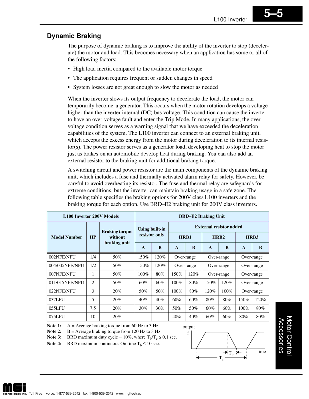
Dynamic Braking
HRB1 HRB2 HRB3
External resistor added Resistor only Model Number Without
Troubleshooting 6 and Maintenance
Troubleshooting
Safety Messages
General Precautions and Notes
Inspection Items
Symptom/condition Probable Cause Solution
Troubleshooting Tips
REV=U-W-V
Signal generating device
Inverter Fault Detection
Previous Error #1
Previous Error #2
Monitoring Trip Events, History, & Conditions
Error Codes
E01
Error Name Causes Code
E35
Restoring Factory Default Settings
Monthly and Yearly Inspection Chart
Maintenance and Inspection
Inspection Item Inspected Check for Cycle Criteria Method
Part description Symbol Quantity Used
Spare parts
Capacitor Life Curve
Operation for 12 hours / day
General Inverter Electrical Measurements
⋅ E1 ⋅
Pf0
⋅ E0 ⋅
Single-phase measurement diagram
Three-phase measurement diagram
Inverter Output Voltage Measurement Techniques
Additional resistor
Warranty
Warranty Terms
Glossary Bibliography
Glossary
Inverter DC braking feature stops the AC commutation to
Components you can install to decrease the level of EMI
Desirable it depends on the needs of the application
Percent of time a square wave of fixed frequency is on high
Unit of time. You can directly convert between horsepower
Watts as measurements of power
Generate 3-phase output to the motor
Harmful harmonics and transients on the input power
Motor speed. See also error
Complex number, where the resistance is the real part
Shaft are rotating and possesses angular momentum
Motor, and control motor speed according to the currently
Energy back to the power input mains
Closely approximate a pure DC voltage source
Desired value. Usually expressed as a percent +/- from
Nominal, motor regulation usually refers to its shaft speed
Power input of the motor. See also rotor
Signal generator usually attached to the motor shaft for
Earth Ground wires accompany the three Hot connections
Loads may be configured in a delta or Y configuration. a Y
Bibliography
Drive Parameter Settings Tables
Main Profile Parameters
Parameter Settings for Keypad Entry
Func. Code Name FE Europe
Standard Functions
Parameter Settings for Keypad Entry
Inverter B22 Overload restriction setting
Fine Tuning Functions
For each
Intelligent Terminal Functions
Monitor Mode Parameters
Parameter Settings for DOP/DRW/DOP Plus
Func Name FE Europe
Function Mode Setup
DEC Line
DCB SW OFF
DCB Wait
IPS Powr ALM
Oload Mode on
THM Char CRT
Oload LVL 01.75A
Oload Const
IN-TM CF1
IN-TM CF2 USP
IN-TM O/C-1
IN-TM O/C-2
Init Mode TRP
Monitor
Init SEL EUR USA
Init Debg OFF
Index
Index-2
Index-3
Index-4