PRIMUSr 880 Digital Weather Radar System
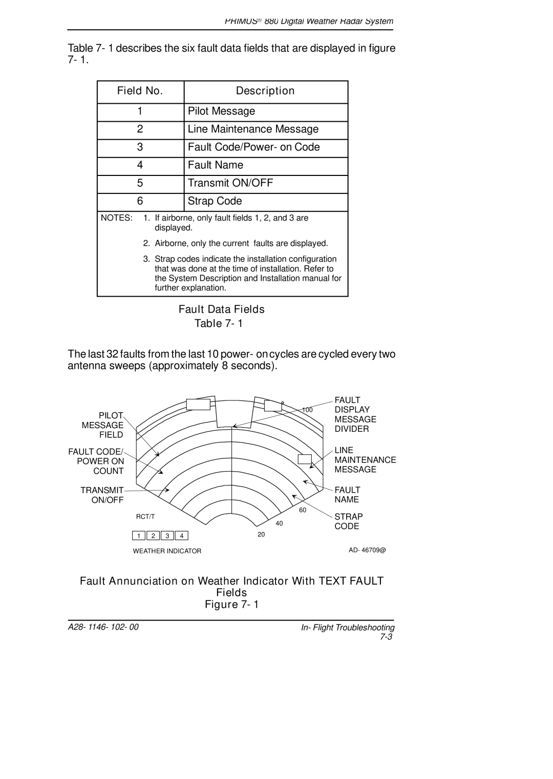
Table 7- 1 describes the six fault data fields that are displayed in figure 7- 1.
Field No. | Description |
|
|
1 | Pilot Message |
|
|
2 | Line Maintenance Message |
|
|
3 | Fault Code/Power- on Code |
|
|
4 | Fault Name |
|
|
5 | Transmit ON/OFF |
|
|
6 | Strap Code |
|
|
NOTES: 1. | If airborne, only fault fields 1, 2, and 3 are |
| displayed. |
2. | Airborne, only the current faults are displayed. |
3. | Strap codes indicate the installation configuration |
| that was done at the time of installation. Refer to |
the System Description and Installation manual for further explanation.
Fault Data Fields
Table 7- 1
The last 32 faults from the last 10 power- on cycles are cycled every two antenna sweeps (approximately 8 seconds).
PILOT
MESSAGE
FIELD
FAULT CODE/
POWER ON
COUNT
TRANSMIT
ON/OFF
RCT/T
1![]()
![]() 2
2 ![]()
![]() 3
3 ![]()
![]() 4 WEATHER INDICATOR
4 WEATHER INDICATOR
| FAULT |
100 | DISPLAY |
| MESSAGE |
| DIVIDER |
LINE
MAINTENANCE
MESSAGE
FAULT
NAME
| 60 |
40 | STRAP |
CODE |
20
AD- 46709@
Fault Annunciation on Weather Indicator With TEXT FAULT
Fields
Figure 7- 1
A28- 1146- 102- 00 | In- Flight Troubleshooting |
|
