PRIMUSr 880 Digital Weather Radar System
20
15
10
GMAP
5
AD- 17722- R1@
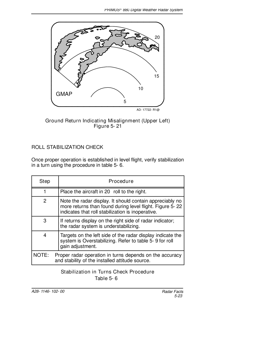
Ground Return Indicating Misalignment (Upper Left)
Figure 5- 21
ROLL STABILIZATION CHECK
Once proper operation is established in level flight, verify stabilization in a turn using the procedure in table 5- 6.
Step | Procedure |
1Place the aircraft in 20°roll to the right.
2Note the radar display. It should contain appreciably no more returns than found during level flight. Figure 5- 22 indicates that roll stabilization is inoperative.
3If returns display on the right side of radar indicator; the radar system is understabilizing.
4Targets on the left side of the radar display indicate the system is Overstabilizing. Refer to table 5- 9 for roll gain adjustment.
NOTE: Proper radar operation in turns depends on the accuracy and stability of the installed attitude source.
Stabilization in Turns Check Procedure
Table 5- 6
A28- 1146- 102- 00 | Radar Facts |
|
