PRIMUSr 880 Digital Weather Radar System
ROLL STABILIZATION CHECK
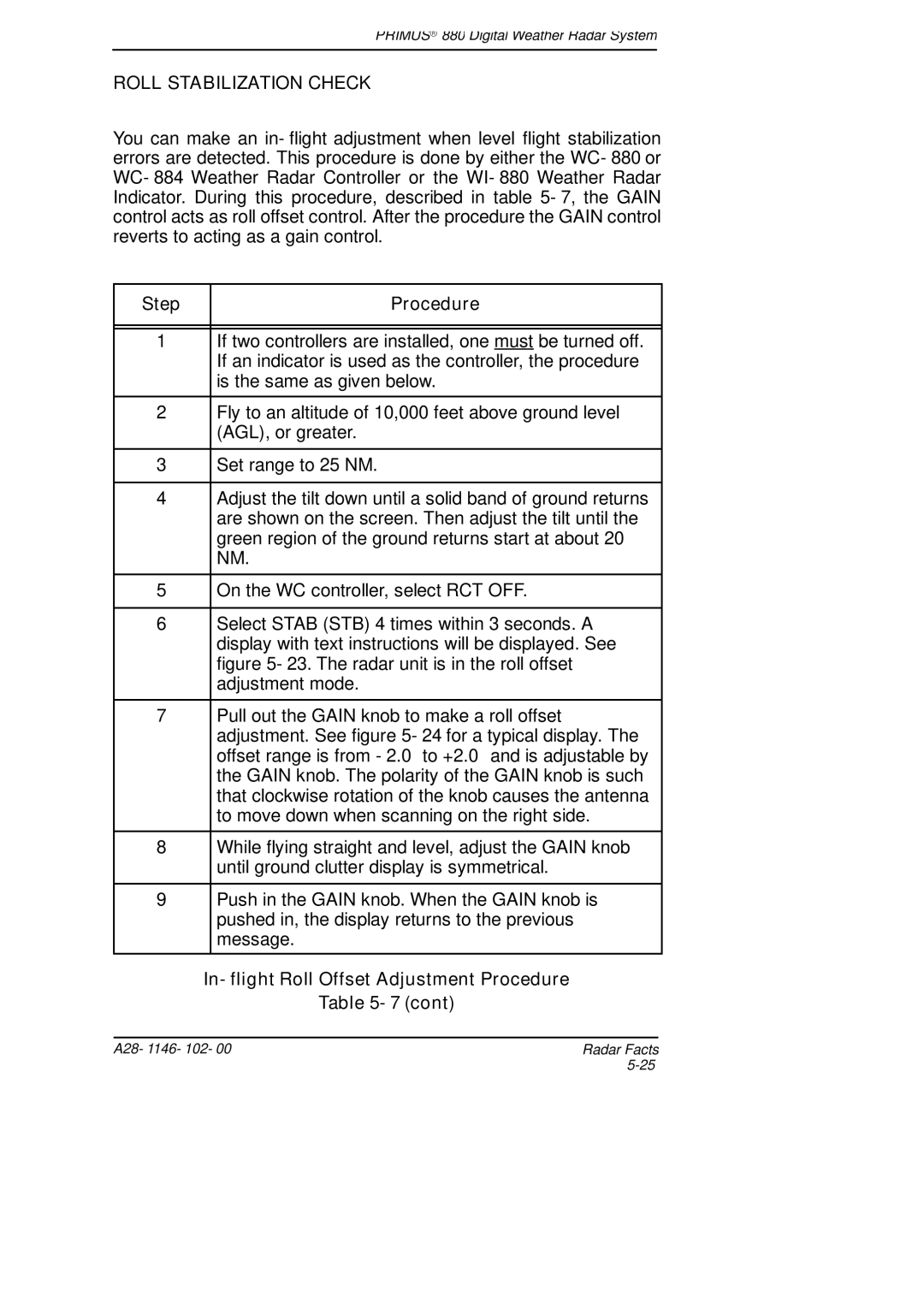
You can make an in- flight adjustment when level flight stabilization errors are detected. This procedure is done by either the WC- 880 or WC- 884 Weather Radar Controller or the WI- 880 Weather Radar Indicator. During this procedure, described in table 5- 7, the GAIN control acts as roll offset control. After the procedure the GAIN control reverts to acting as a gain control.
Step |
| Procedure |
|
|
|
|
|
|
1 |
| If two controllers are installed, one must be turned off. |
|
| If an indicator is used as the controller, the procedure |
|
| is the same as given below. |
2 |
| Fly to an altitude of 10,000 feet above ground level |
|
| (AGL), or greater. |
|
|
|
3 |
| Set range to 25 NM. |
|
|
|
4 |
| Adjust the tilt down until a solid band of ground returns |
|
| are shown on the screen. Then adjust the tilt until the |
|
| green region of the ground returns start at about 20 |
|
| NM. |
|
|
|
5 |
| On the WC controller, select RCT OFF. |
|
|
|
6 |
| Select STAB (STB) 4 times within 3 seconds. A |
|
| display with text instructions will be displayed. See |
|
| figure 5- 23. The radar unit is in the roll offset |
|
| adjustment mode. |
|
|
|
7 |
| Pull out the GAIN knob to make a roll offset |
|
| adjustment. See figure 5- 24 for a typical display. The |
|
| offset range is from - 2.0°to +2.0°and is adjustable by |
|
| the GAIN knob. The polarity of the GAIN knob is such |
|
| that clockwise rotation of the knob causes the antenna |
|
| to move down when scanning on the right side. |
8 |
| While flying straight and level, adjust the GAIN knob |
|
| until ground clutter display is symmetrical. |
|
|
|
9 |
| Push in the GAIN knob. When the GAIN knob is |
|
| pushed in, the display returns to the previous |
|
| message. |
| In- flight Roll Offset Adjustment Procedure | |
|
| Table 5- 7 (cont) |
A28- 1146- 102- 00 | Radar Facts |
|
