PRIMUSr 880 Digital Weather Radar System
Table of Contents (cont)
List of Illustrations (cont)
Figure |
| Page | |
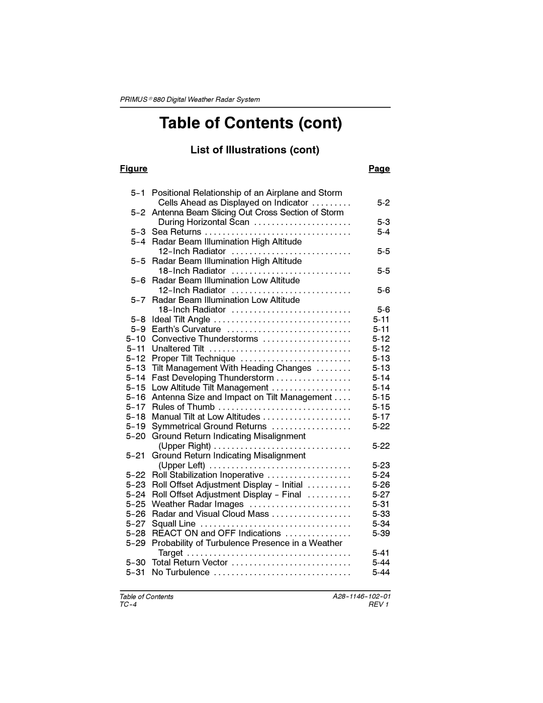
5 | Positional Relationship of an Airplane and Storm |
| |
|
| Cells Ahead as Displayed on Indicator | |
5 | Antenna Beam Slicing Out Cross Section of Storm |
| |
|
| During Horizontal Scan | |
Sea Returns | |||
5 | Radar Beam Illumination High Altitude |
| |
|
| ||
5 | Radar Beam Illumination High Altitude |
| |
|
| ||
5 | Radar Beam Illumination Low Altitude |
| |
|
| ||
5 | Radar Beam Illumination Low Altitude |
| |
|
| ||
Ideal Tilt Angle | |||
Earth’s Curvature | |||
Convective Thunderstorms | |||
Unaltered Tilt | |||
Proper Tilt Technique | |||
Tilt Management With Heading Changes | |||
Fast Developing Thunderstorm | |||
Low Altitude Tilt Management | |||
Antenna Size and Impact on Tilt Management . . . . | |||
Rules of Thumb | |||
Manual Tilt at Low Altitudes | |||
Symmetrical Ground Returns | |||
20 | Ground Return Indicating Misalignment |
| |
|
| (Upper Right) | |
21 | Ground Return Indicating Misalignment |
| |
|
| (Upper Left) | |
Roll Stabilization Inoperative | |||
Roll Offset Adjustment Display | |||
Roll Offset Adjustment Display | |||
Weather Radar Images | |||
Radar and Visual Cloud Mass | |||
Squall Line | |||
REACT ON and OFF Indications | |||
29 | Probability of Turbulence Presence in a Weather |
| |
|
| Target | |
Total Return Vector | |||
No Turbulence | |||
|
|
|
Table of Contents | ||
REV 1 | ||
