Smile SDC heating and district heating controller
EN2H-0221GE51 R0808
Contents
Menu-selection level
SDC / DHC
Control Functions 114
Hydraulic Components 128
155
171
255
Technical data 250
254
SDC / DHC
Intended use
Software version
Cable cross-sections
Power supply
Cable installation
Connection conditions
Grounding and zeroing
Hot-water temperature greater than 60 C
SDC / DHC
Safety precautions for EMC-compliant installation
SDC / DHC
SDC / DHC
SDC / DHC
SDC / DHC
Overview
Abbreviations
Display and operating elements
Operation
Display basic display
Setting range
Daytime room temperature button
Setting
Factory setting
Factory setting 50 C
Night-time room temperature button
Factory setting Setting range 2.4
Daytime hot-water temperature button Setting
Operating mode button basic display
Setting range One-time hot-water circuit loading
Summer
Absent
Party
Automatic
Absence mode short-term program
Setting Return to the basic display
P1 P2, P3
Party mode short-term program
Automatic mode
Manual summer operation excluding heating operation
Display 2.5.4 Disabling / enabling default program P2 to P3
Disabling / enabling default programs P2 to P3
Enabling
Continuous lowering operation
Continuous heating operation
Switching time programs / Holiday programs button
Holiday mode
System information button
Factory setting Current date
Operating overview
EM-SET
Temperature displays Information Display Condition Remarks
OFF
ON/OFF
Information Display Condition Remarks
MC2
Thermostat
MC1
Information Display Condition
Operating states
Information Display Condition
Clock
Information Display Condition
Cancellation Press
Manual mode / Emission measurement button
SDC / DHC
Procedure
Access to the technician / OEM area
2.10 Setting Setting range Heating curve
Menu-selection level
Parameter Programming Date
Parameter Programming Date Hydraulics
Parameter Programming Date Hydraulics Configuration
Hot water Direct heating Circuit Mixed heating
Parameter
Returning
Access
Time Date menu
Timeprograms menu Access Returning
Selection of day of the week and cycle
Selection of the control circuit
Selection of the program
Switch-off time
Cycle temperature
DHW
Switching time programming programs P2 and P3 disabled
Default program P1
Default switching time program P1 for heating and hot water
Switching time programming program P2 and P3 enabled
Default program P3
Default program P2
Calling up the copy function days
Copying switching time programs days Source day Target day
Calling up the copy function heating circuits
Block programming
SDC / DHC
DHW
Copying heating circuits
Reloading default programs
SDC / DHC
Reloading default programs
Switching time programs P2 and P3 enabled
System information button, pg Language selection
System Parameters menu Access Returning
Setting values DE
Factory setting German
Time program
Set values Factory setting Effects
Control mode selection
Switching time programming
Setting range
Individualised operating mode for each heating circuit
Parameter reset
Quick increase in outside temperature
Slow increase in outside temperature
Factory setting 20 C
DHW menu
Complete reset
ALL
Night-time hot-water temperature
Factory setting 40 C
ECO, RED
ECO switch-off operation
Reduced operation
ECO
Conv
Heating system
UFH
RAD
Factory setting Setting
Parameter settings Hydraulics menu Hydraulic
Para Designation Setting range / Setting values Meter
Mixed heating
Electrical heating circuit
Buffer sensor
Setting System parameters menu System
ALL
OFF, on
OEM
RTC
SDC, DHC
SDC/DHC
Hot-water circuit menu DHW
SDC / DHC
Auto
CON
Direct heating circuit menu Unmixed Circ
RED
Room connection
Stby
Mixed heating circuit 1 / 2 MIX.VALVE 1 / MIX.VALVE 2 menus
Room connection
SDC / DHC
Room control Tn 240 min SDW 30 only Holiday operating
Heat generator menu Heat Gener
Unlimited minimum limit
SLT
102 EN2H-0221GE51 R0808
OFF Reset
Reset
District hot water menu DIST.HEATING
Return increase menu Return Contr
Solar menu Solar
Solid menu Solid Fuel
Buffer menu Buffer
Total flow regulation menu Main Supply
Cascading menu Cascade
STOP-OPEN-CLOS Stop
Data bus menu BUS
Relay test menu Relay Test
OFF-ON-OFF
Error messages menu Alarm
Sensor calibration menu Sensor ADJ
Error messages 2 menu Alarm
Control Functions
Example
DKP, VA1 VA2
SLP
VF2
SLP, DKP
Slvf
Switching time program enabling
FKF
Sslp
Enabling Separate Control Mode
Suppressing the cycle temperature on time program level
Variable inputs and outputs of device series SDC/DHC
Switching from SDC to DHC
Selection of hydraulic parameter presettings
Application
Parameter
Key/Menu
System
Climate zone
Outside temperature disable
Design temperature
Outside temperature rise
Summer switch-off
System frost protection
Cancelling switch-off
Operation without room temperature sensing
Cycle operation
Operation with room temperature sensing
Frost protection function in case of heat generator fault
Pump forced operation
Start-up protection controlled by weather conditions
Heat generator Boiler Heat generator start-up protection
Unlimited start-up protection
Unlimited minimum limit
Heat generator minimum temperature limit
Minimum limit based on demand
Conditional minimum limit
External burner switch-off
Heat generator sensor control mode
Burner switch-off in case of a faulty heat generator sensor
Minimum burner runtime
Burner enabling in case of a faulty heat generator sensor
Switching Multi-stage heat generator/Switching differential
Mode of operation with switching differential
Combined operation for 2-stage heat generators
Time-out during start-up relief
Unlimited enable during start-up relief
Resetting
Operation for modulating burners
Modulation of sample time Ta
Modulation of P part Xp
Modulation of start time
Modulation of integral action time Tn
Modulation of runtime
Modulation of start power
OpenTherm logo Electrical connection
OpenTherm
Dissipation into hot-water tank
Two measuring points in the combustion chamber
External heat generator cut-off
Set values OFF
Heat generator lock if limit value is exceeded for set time
Exhaust gas temperature monitoring
Display of flue gas temperature only
Discharge to heating circuits
Burner counter mode
Recommended setting
Heat generation, heat exchanger, district heating
Para Designation Range Presetti Step Unit Meter Increase
Continuous heat exchanger valve control
1 On/Off operation of the district heating valve
Para Designation Range Presetti Step Unit Meter
District heating return temperature limit
SDC / DHC
Para- Designation meter
Range Pre Step Unit Setting
Return temperature limit for hot-water loading
Hot-water pre-regulator with district heating systems
Mode of operation Hot-water pre-control
New parameters
Quick hot-water control
SDC / DHC
SDC / DHC
Conditional parallel operation for mixed heating circuits
Circulation pump control mode
Return interval flushing
Switch-off of district heating control
Charging pump CHP
Boiler circuit pump
Primary pump
Return increase
Bypass pump RBP
Return maintenance through controlled feed water addition
Indirect return increase
Heating curve setting heating curve
Recommended settings
Heating circuit temperature limit
SDC / DHC
SDC / DHC
Heating function for floor covering setting
Function heating acc. to DIN 4725 Part 4 setting
Fixed-value control
Heating circuit constant temperature control
No room sensor with the following conditions
Heating circuit room factor
Heating circuit room controller
Switch-on/switch-off optimisation
Parameter settings for the switch-on optimisation in the HC
On optimisation
Activation of switch
Parameter 41 switch-on optimisation, 03 adaptation restart
Parameter 44 min. jump back temperature
Parameter 47 lowering ramp
Switch-on optimisation with room sensor adaptation
Switch-on optimisation without room sensor
Parameter 46 pre-heating time at 0C
Heating limit function
Room setpoint ramp
Example
Wall device functionality limitation
Mixed heating circuits cooling switch-over
Heating circuit room frost protection limit Function
Heating circuit correction
Switch-over from heating mode to cooling mode
Cooling with humidistatic switch-off
Humidistatic switch-off
Heating circuit name Access code
Room thermostat function maximum room temperature limit
Mixed heating circuit control Proportional part Xp
Integral action time Tn
Actuator runtime
Application Adjustment Time
Sample time Ta
Example
Actuator end position function
Example After
See also 5.1.2.4 Daytime hot-water temperature button, pg
Hot-water production Hot-water tank loading SLP
Example Before
SDC / DHC
SDC / DHC
SDC / DHC
SDC / DHC
Quick hot-water connection in cascaded systems
Tank priority no heating demand
Heating
Circulation pump CIR
Electrical heating element ELH
Solar/Solid fuel/Buffer Solar function
Solar switch-on differential
Solar parallel operation
Solar priority mode disabling of heat generator
Solar priority mode hot water setpoint control
Solar priority mode buffer setpoint control
Operation in buffer priority mode
Buffer tank function
SDC / DHC
SLP
PLP
SLP SF
SLP
Buffer HC/HW
Buffer control mode
HC/HW
Buffer control mode
Discharge control
Loading control
Example
Tank loading pump with provision tanks only
Set value OFF
SDC / DHC
Buffer loading pump extended running time
Buffer sensor 2 BS2 Buffer sensor 2 BS2
Solid fuel function
Solid-fuel boiler minimum temperature limit
Prerequisite
Heat generator solid-fuel cycle disable
Tank loading switch-over
Solar loading switch-over operation
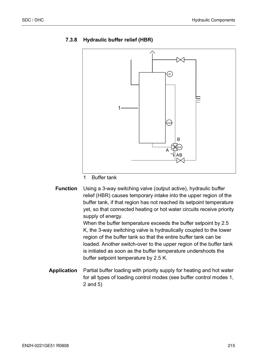
Hydraulic buffer relief HBR
Kspf B
Setting range OFF, -20 +30
Timer
Other system components Global fault message input
Global fault message output
HEATING, HEATING, Standby
External switching modem
Connection terminal of variable input 1 2, 3 open
Demand contact
System information
Address Device type Assignment
Bus communication Bus address of central device
Clock synchronisation
Tank control mode tank priority operation
Heating circuit demand
Examples with multiple control devices
Room temperature transmission
Fault messages/Status indications
MK1
Important note for parameter setting
226 EN2H-0221GE51 R0808
Address CD address Assignment
Address CU address Assignment
Operation with wall device SDW
Automatic Mode Heating Lowering Automatic
Flashing OFF
Control mode/Function Moon LED Clock LED Sun LED
Brief Flashing
OFF Flashing
Operation with NTC 20K room temperature sensor
Extended access authorisation
Function of the cascade parameters
Switch-off characteristics
Delay, enabling, full load in cascade operation
Control characteristics
Special function characteristics
Grouping for base and peak loads ANF118-V2.2 specifications
Automatic call-up
Emission measurement not for DHC
Input Only executed if
Relay/function test
2x single-stage heat generators
Modulating mode
Single-stage heat generator
Stage heat generator
Meaning Display
Value Range
Bus test
SDC / DHC
Fault messages
Eeprom
RSC/RS
These fault messages come from automatic stokers and are
LOW
Additional fault processing
Fault type Field Code
High
Operating Key/Menu Parameter Information
Fault Message
Basic display/fault stack fault messages
Controller time correction
Full controller reset
Sensor calibration
III
Technical data
Sensor resistance values 1 NTC
Installation recommendations Mains voltage lines
Safety low-voltage lines
VE2
2 PT
VF1
VE1
BZ2
BZ1
Log
Index
SDC / DHC
SDC / DHC
Automation and Control Solutions