Honeywell
Rev. A
HSVR-04 HSVR-16 Digital Video Recorder
User Manual
Page
Contents
Honeywell
Honeywell
Preset/Tour/Pattern/Scan Operations
5 Understanding of Menu Operations and Controls
Honeywell
Important Safeguards and Warnings
Welcome
∙ User manual ∙ Remote controller
∙ Software CD ∙ USB mouse ∙ Network cable ∙ 12VDC power adapter
∙ Power cord ∙ SATA data cable and screws for HDD installation
∙ 4 BNC connectors only in HSVR-04 package ∙ HDMI cable
1 Features and Specifications
Features
Overview
Features and Specifications
Specification
Supports monitor touring modes alarm
Covers secret channel with blue screen though system is encoding
Ordinary serial port for upgrade and maintenance and transparent
Authentication when shut down to make sure only authorized users
0-+55
Figure 2-1 The Front Panel of HSVR-04/HSVR-16
2 Overview and Controls
Front Panel
Name
Overview and Controls
ENTER
Figure 2-2 The Rear Panel of HSVR-04
Rear Panel
Alarm
Figure 2-3 The Rear Panel of HSVR-16
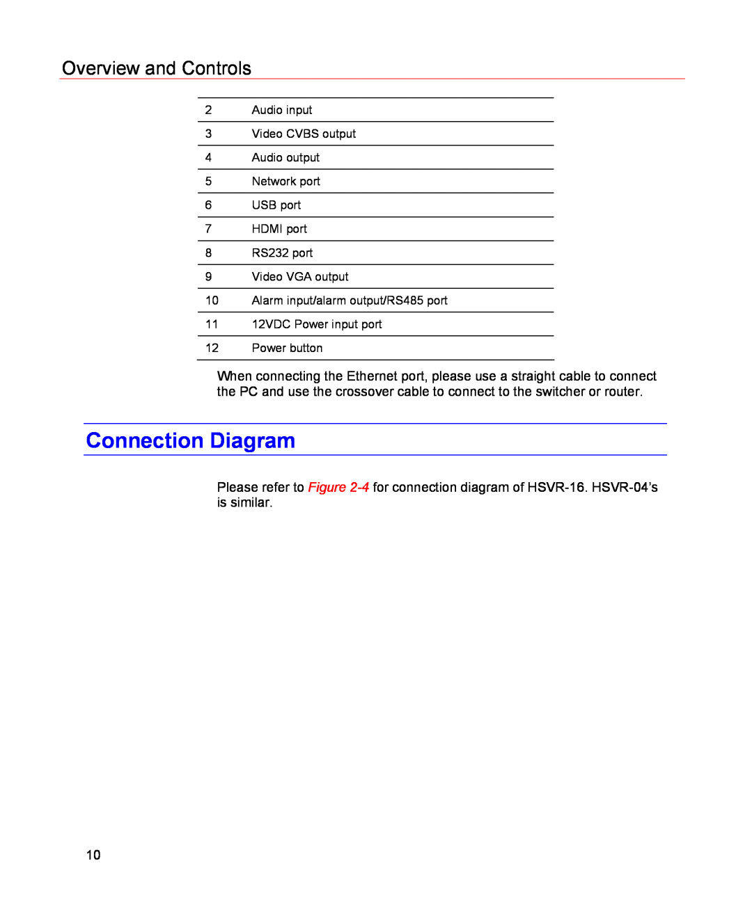
12 Power button
Connection Diagram
10 Alarm input/alarm output/RS485 port 11 12VDC Power input port
2 Audio input 3 Video CVBS output 4 Audio output 5 Network port
Remote Controller
Figure 2-4 Device Connection
Figure 2-5 Remote Controller
Left click mouse
Mouse Control
The password input dialogue box will pop up if you have not logged in
In real-time monitor mode, you can go to the main menu
In English input mode stands for input a backspace icon and
In real-time monitor mode, the shortcut menu will appear one
Installation and Connections
3 Installation and Connections
HDD Installation
Check Unpacked DVR
Please follow the instructions below to install the hard disk
Connecting Video Input
Connecting Power Supply
Connecting Video Input and Output Devices
Guarantee the stability and reliability of the camera signal
Audio Input
Connecting Audio Input & Output
Connecting Video Output
Audio Output
Alarm Input and Output Connection
Alarm Input and Output Details
Alarm Input Port
Figure 3-1 Alarm Input and Output of HSVR-04 Left and HSVR-16 Right
Alarm Output Port
Figure 3-2 Sample of Alarm Input Normal Close Type
RS232
RS485
Figure 3-3 PTZ Connection Port
Login, Logout & Main Menu
Login
4 Overview of Navigation and Controls
Figure 4-1 Menu Login
Overview of Navigation and Controls
Main Menu
Figure 4-2 Main Menu
Logout
Auto Resume after Power Failure
Replace Button Battery
Figure 4-3 Logout Menu
Manual Record
Manual Record
Live Viewing
Manual Record Menu
Figure 4-5 Recording Control Menu
Enable/disable recording in specified channels
Enable/disable recording in all channels
Figure 4-6 Different Status of Manual Record
Stop all channel recording
Figure 4-7 Automatic Recording in All Channels
Figure 4-8 Start Manual Record in All Channels
Figure 4-9 Stop Recording in All Channels
Search & Playback
Search Menu
See Figure
Please refer to the following chart for more information
Figure 4-10 Record Search Menu
Serial Number
Basic Operation
Synchronized playback function when playback
File backup
Playback
Calendar
Backward playback and frame by frame playback
Schedule
Schedule Menu
Figure 4-11 Sample of the Calendar
Go to Detect Menu
Quick Setup
Detect
Figure 4-12 Schedule Menu
Motion Detection
Figure 4-13 Motion Detection Menu
Figure 4-14 Motion Detection Zone Setting
Figure 4-15 PTZ Activation Setting
Figure 4-17 Business Day and Non-Business Day Setting
Video Loss
Figure 4-16 Armed Period Setting
Tips
Camera Masking
Figure 4-18 Menu of Video Loss
Alarm setup
Alarm Setup and Alarm Activation
Go to alarm setup interface
Figure 4-19 Menu of Camera Masking
Honeywell
Figure 4-20 Menu of the Alarm
Figure 4-21 The settings of PTZ Activation
Figure 4-22 Period Setup
Backup
Detect Device
Figure 4-23 The Settings of Business Days and Non-Business Days
Backup
Figure 4-24 Device Detection Menu of Backup
Figure 4-25 Backup Menu with Search Results
Figure 4-26 Backup in Progress
PTZ Control and Color Setup
PTZ Setup
Cable Connection
∙ Protocol Select the corresponding PTZ protocol such as PELCOD
Figure 4-28 The Context Menu
Figure 4-29 PTZ Control Menu
Preset/Tour/Pattern/Scan Operations
PTZ Trace
Figure 4-30 PTZ Setup Menu
∙ Preset ∙ Tour ∙ Pattern ∙ Auto scan ∙ Auto pan
Figure 4-31 Function Menu
Figure 4-32 Preset Setup
Preset Setup
Activate Preset
interfaces shown in Figure 4-29 , Figure 4-30 and Figure
Activate Patrol tour
Patrol setup Tour Setup
Pattern Setup
Figure 4-33 Tour Setup
Figure 4-34 Pattern Setup
Auto Scan Setup
Activate Pattern Function
Figure 4-35 Auto Scan Setup
Activate Auto Scan
Click Page Switch again, and the system will go back to Figure
5 Understanding of Menu Operations and Controls
Menu Tree
General Encode Schedule RS232 Network Alarm Detect Pan/ Tilt/Zoom
Understanding of Menu Operations and Controls
Search page Information HDD Info BPS Log Version Online Users Setting
Display Default Backup page45 Advanced HDD Management Alarm Output
General
Setting
Main Menu
Figure 5-1 The Main Menu - Setting
∙ Time format There are two types 24-hour mode or 12-hour mode
Encode
Figure 5-2 General Setup Menu Figure 5-3 DST Setup Menu Weel
Figure 5-4 DST setup menu Date
Note that some series do not support extra stream
Schedule
RS232
Figure 5-5 Encode Menu Figure 5-6 Overlay Menu
Network
Figure 5-7 The RS232 Setup Menu
Advanced Setup
Figure 5-8 Network Setup Menu
Figure 5-9 Advanced Settings
IP Filter
PPPoE
Figure 5-10 IP Filter Menu
NTP Setup
Figure 5-11 The PPPoE Setup Menu
DDNS Setup
Figure 5-12 The NTP Setup Menu
Figure 5-13 The DDNS Setup Menu
Figure 5-14 The FTP Server Setup Menu
Figure 5-15 The FTP Login Window
Email
Figure 5-16 The FTP Setup Menu
Figure 5-17 The Email Setup Menu
Pan/Tilt/Zoom
Alarm
Detect
Figure 5-18 The Command Window
Display
Figure 5-19 The PTZ Setup Menu
Figure 5-20 The Display Setup Menu
Figure 5-21 The Channel Name Setup Menu
Figure 5-22 The Sample of Tour Mode
Default
Advanced
Figure 5-23 The Default Setup Menu
HDD Management
Figure 5-24 The Advanced Menu
Figure 5-25 The HDD Management Setup Menu
Abnormity
Figure 5-26 The Abnormity Setup Menu
Alarm Output
Figure 5-27 The Sample of No Disk Abnormity
Account
Figure 5-28 The Alarm Output Setup Menu
Auto Maintain
Figure 5-29 The Account Management Menu
TV Adjust
Figure 5-30 The Auto Maintain Setup Menu
Figure 5-31 The TV Adjust Menu
Information
HDD Information
Figure 5-32 The Info Menu
Figure 5-33The HDD Info Menu
Figure 5-34 The BPS Display Menu
Version
Figure 5-35 The Log Search Menu
Online Users
Figure 5-36 The Version Menu
Shutdown
Figure 5-37 The Online Users Menu
Figure 5-38 The Shutdown Menu
Login
6 Web Client Operation
Network Connection
Web Client Operation
Figure 6-1 Sample of IE Login
Figure 6-2 The Internet Options Window
For security reasons, please modify your password after
you first login
Figure 6-3 The Settings for ActiveX
Figure 6-4 The Web Login Window
Figure 6-5 The Window Switch Menu
Figure 6-7 The Main Menu of Web Client
Real-Time Monitor
Figure 6-6 The Preview Window Switch Menu
Figure 6-8 Status Information
Open All
Figure 6-9 Control Setup
Figure 6-10 Switch between the Main Stream and Extra Stream
Refresh
Local Play
Figure 6-11 Selection Menu of Local Play File
Zoom/Focus/Iris
Direction key and 3D positioning key
Speed
Figure 6-12 PTZ Control Menu
Pattern
Preset
Auto Scan
Figure 6-13 The PTZ Setup Menu
Assistant
Color
Auto tour
Figure 6-14 The Assistant Setup Menu
Figure 6-16 The More Setup Menu
Picture Path and Record Path
Figure 6-15 The Color Setup Menu
Figure 6-17 The Path Setup Menu for Picture
Version Information
Configuration
System Information
Figure 6-18 The Path Setup Menu for Record
HDD information
Figure 6-20 Version Information Menu
Figure 6-21 HDD Information Menu
Figure 6-22 Log Information Menu
Click Backup, and the interface is shown in Figure
Figure 6-23 Log Backup Menu
Please refer to the following sheet for log parameter information
System Configuration
General Setup
Figure 6-24 General Setup Menu
Figure 6-25 DST Setup Menu Date Figure 6-26 DST Setup Menu Week
time. See Figure 6-25 and Figure
Encode
Figure 6-27 The Encode Menu
Figure 6-28 The Color Setting Menu
Click copy interface, the interface is shown as in Figure
Schedule
Figure 6-30 The Schedule Setup Menu
Figure 6-29 The Copy To Menu
Figure 6-31 The Date and Time Setup Menu
in Figure
RS232
Figure 6-32 The RS232 Setup Menu
Parameter Function
System default setup
Network
Figure 6-33 The Network Setup Menu
Figure 6-34 The Email Setup Menu
DDNS
Figure 6-35 The DDNS Setup Menu
Figure 6-36 The NAS Setup Menu
The NTP interface is shown in Figure
Alarm
Figure 6-37 The NTP Setup Menu
Figure 6-38 The Alarm Setup Menu
Detect
page 35 and Manual Record on page
Figure 6-39 The Detection Setup Menu
Figure 6-40 The Detection Zone Setup
Parameter
Figure 6-41 The PTZ Setup Menu
Default & Backup
Default setup is 8. Please set according to the speed dome dial
Default setup is 1. Please set according to the speed dome dial
Advanced
HDD Management
Figure 6-42 The Default Setup Menu
Alarm I/O
Figure 6-43 The HDD Management Menu
Record
Figure 6-44 The Alarm I/O Config Menu
Account
Figure 6-45 The Record Control Menu
Auto Maintenance
Figure 6-46 The Account Management Menu
Abnormity
Figure 6-47 The Auto Maintenance Menu
Figure 6-48 The Abnormity Setup Menu
Search
Figure 6-49 The Record Search Menu
Figure 6-50 The Record Save Menu
Figure 6-51 The Record Search Menu Saving
Figure 6-52 The Message Box after Download Completed
Type
Download
Alarm
The IP address of playback device and channel number
Figure 6-53 The Playback Menu
Figure 6-54 The Alarm Function Menu
About
Log out
Figure 6-55 The Web Client Information
Un-install Web Control
Figure 6-56 The Logout Interface
7 FAQ
There are the following possibilities
Page
Honeywell
Page
Honeywell
Slight difference may be found in user interface
Please visit our website for more information
8 Appendix
HDD Capacity Calculation
q i = d i ÷ 8 × 3600 ÷1024
Compatible USB Drive List
Appendix
FAX +86
35F Tower A, City Center, 100 Zun Yi Road, Shanghai 200051, China
TEL +86 21
Block 28, Section