Multi-Media Unit
Page
Issue Date Revisions
Page
Declaration of Conformity
Page
Table of Contents
Index
Frequent Questions
Find-it
Page
Page
Overview
New to Multi-Media?
Not new to Multi-Media?
Software
Communications
Walking Through
Cameras
Other Hardware
Powering-up the Multi-Media unit
Admin and View Software
Start Admin to create a Multi database
Log on to a Multi database, or create one using Admin
Using Admin, add a site
Database for Multi
Type of Connection
Running View
Add information about the connection, and save it
About connections
Log on to View
Testing a Connection
Test the connection use View to run a Maintenance session
Where To, Next?
For More Information
Background information
Unpacking the Unit
Audience
Road map to field work
Please do not remove factory seals on a Multi-Media unit
Printed matter
Rear Panel Reference
Item, one of each, unless otherwise noted
Temperature
USB port and Printer port
Reporting the Installation
Powering the Multi-Media Unit
Powering Up and Down
Connecting a Camera
Unit Recovery
Nominal storage* camera-day time† minute
Rapid Dome or Rapid Dome Gold dome systems
LocalView
Securing a camera
Reference
Hardware
Monitors
To enable the locking of a LocalView functions
LocalView help on operator’s PC
To change a LocalView password
Network Connection
Recording rate fps lowest cycle time sec
Overview
Using LocalView Onsite
To assign an IP address to a unit using LocalView
For a network without Dhcp
What next?
Using a PC Onsite
To setup a terminal program
To connect a null-modem cable
Null-modem cable comes with your Multi-Media unit
Multi-Media Unit Installation Instructions
Windows Click Start and point to … … then click
Hypertrm.exe icon
Parameter Value
To use the Multi-Media Shell
Field Name Default Address Shell command
Command Result
Multi Shell Reference
None, port1, port2, or internal
Dial-up Connection
To return to the Multi-Media Shell after a time out
Modem Reference
Field Testing a Connection
Damaged or Missing Goods
Upgrade CD-ROM
To upgrade a Multi-Media unit’s software, onsite
Upgrading Unit Software
Multi-Media unit without a CD-RW drive
Please continue
Multi Software
Road map for using Multi software to obtain video
Why check a connection?
To install Multi software
Some versions of Windows need you to restart the PC
Using Admin
Running Admin
Double-duty logon dialog
Obtaining a Multi Db
After adding security
Click Save and Close To name a site
Site identification checklist
Adding Site Information
Record of a Dial-up Connection
Dealing with connections
Confirmation
To make a record of a dial-up connection
Dealing with dial-up confusion
IP Address is mandatory for a network connection
Record of a Network Connection
To make a record of a network connection
Checking for video
Using View to Connect
Firewall reference
Testing a Connection Maintenance
Using Maintenance
To run a maintenance session on a Rapid Eye site
Logging on to View
Time zone
Testing a Connection Time
Crucial settings for reporting on video of events
Conflicting time zones
To indicate the time zone of a Multi-Media unit
Time zone is set on a unit-by-unit basis
Clock Automatic setting
To respond to a notification of conflicting time zones
To set a unit’s clock manually, using a PC’s
Auto-synch statistics
Testing a Connection Camera
Video tab in Maintenance session video feed adjustments
To obtain video from a live video session
To configure a Rapid Eye site’s cameras
Obtaining Video
Results
What Next
Please continue
Audio at a Multi-Media Site
Microphones
Selecting a microphone
Placing a microphone
Checking for Audio Interference
Preventive measures
To enable talking to a site
Audio for Operators
At View Operator’s PC
To send and receive audio offsite
To enable audio for use onsite, by LocalView
To disable audio for LocalView
Securing a Multi-Media unit
To secure the unit
Unit Hard Disk
Detachable Camera I/O
Hard Disk Report
To detach the sub-panel
Hardware Options
Handle on mounted hard disk
Daisy-chaining Domes
Connecting a PTZ Dome
Converter Technical Notes
Configuring PTZ
Driver name Baud rate Supported controller/dome Alphabetical
Alarm Sensors
Inputs for Sensors
Input Technical Notes
Inputs to a Multi-Media unit, used by hardware devices
No normally open
NC normally closed
Control Outputs
System Monitoring
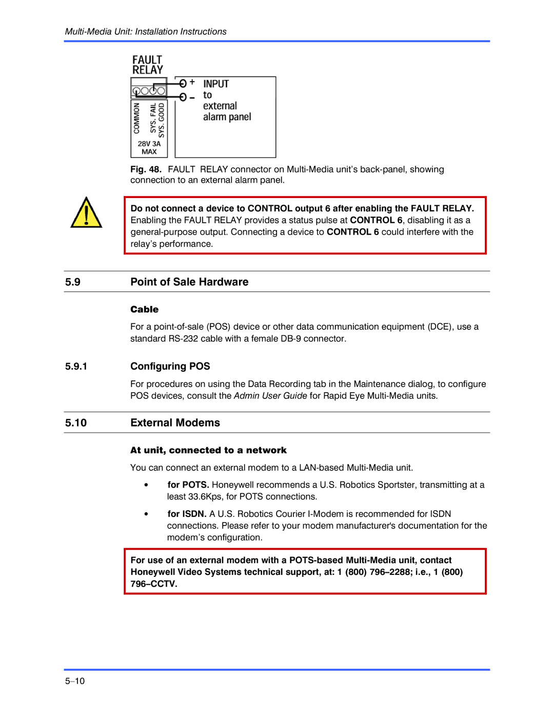
Alarm panel
Software setup To set the Fault Relay to trigger
Configuring POS
Point of Sale Hardware
External Modems
At unit, connected to a network
Using null-modem cable for installation of Multi-Media unit
Port Use Restrictions
Serial connection Connect only to serial port COM
USB port and Parallel port
Please continue
Supporting an Installation
Cannot connect to Multi-Media unit, using View
Background
Frequently asked question Section No video is reaching View
See also
Planning
Coaxial Cable
Grounding
Electrical Interference
Lighting
Hum bar
Triaxial cable
Find-it
Knowledge Base
Tables
Use the same database created earlier, using Admin see on p
Illustrations
Dial-up Networking
More FAQs
More FAQs Find-it
Network Connection
More FAQs Find-it
Site Information Checklist
Organization personnel Personnel Name, telephone #, email
Site definition Rapid Eye site… Identification
Communications to unit Connection Value
Audio Microphone type Speaker type Comments
Site Information Checklist Find-it
Sensor hardware Input Type NO, NC, EOL Description
Site Information Checklist Find-it
Multi-Media Unit Installation Instructions
Index
Multi-Media Unit Installation Instructions
Index
Page
Page
Page
Page
Honeywell Security France
Honeywell Security Italia SpA
Honeywell Security Espana
Honeywell Security House Netherlands