EXCEL 10 W7761A INPUT/OUTPUT DEVICE
∙Make earth ground connections with the shortest possible wire run using 14 AWG (2.0 mm2) wire. A good earth ground is essential for W7761A operation. Ideally, connect the earth ground to the ground bus at a motor control center or circuit breaker panel. However, if the nearest ideal earth ground is inaccessible, consider an alternate source for earth ground. Metal water pipe is generally a good ground, but do not use sprinkler pipe if prohibited by local codes. Attention must be given when duct work, conduit, or rebar are to be considered as ground sources. It is the responsibility of the installer to assure that these structures are tied back to a known earth ground.
Step 4. Prepare Wiring Diagrams
General Considerations
The purpose of this step is to assist the application engineer in developing job drawings to meet job specifications. Wiring details are included for the W7761A device the T7770A,B,C,D wall module
NOTE: For field wiring, when two or more wires are to be attached to the same connector block terminal, be sure to twist them together. Deviation from this rule can result in improper electrical contact. See Fig. 15.
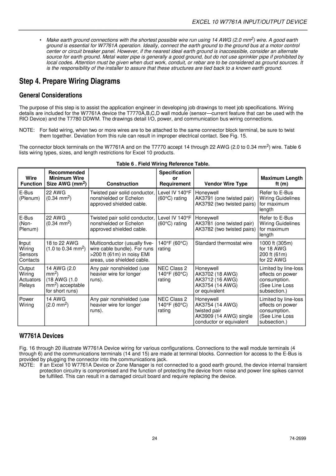
The connector block terminals on the W7761A and on the T7770 accept 14 through 22 AWG (2.0 to 0.34 mm2) wire. Table 6 lists wiring types, sizes, and length restrictions for Excel 10 products.
Table 6 . Field Wiring Reference Table.
Wire | Recommended |
| Specification |
|
|
Minimum Wire |
| or |
| Maximum Length | |
Function | Size AWG (mm2) | Construction | Requirement | Vendor Wire Type | ft (m) |
22 AWG | Twisted pair solid conductor, | Level IV 140°F | Honeywell | Refer to | |
(Plenum) | (0.34 mm2) | nonshielded or Echelon® | (60°C) rating | AK3791 (one twisted pair) | Wiring Guidelines |
|
| approved shielded cable. |
| AK3792 (two twisted pairs) | for maximum |
|
|
|
|
| length |
|
|
|
|
|
|
22 AWG | Twisted pair solid conductor, | Level IV 140°F | Honeywell | Refer to | |
(Non- | (0.34 mm2) | nonshielded or Echelon® | (60°C) rating | AK3781 (one twisted pair) | Wiring Guidelines |
Plenum) |
| approved shielded cable. |
| AK3782 (two twisted pairs) | for maximum |
|
|
|
|
| length |
|
|
|
|
|
|
Input | 18 to 22 AWG | Multiconductor (usually five- | 140°F (60°C) | Standard thermostat wire | 1000 ft (305m) |
Wiring | (1.0 to 0.34 mm2) | wire cable bundle). For runs | rating |
| for 18 AWG |
Sensors |
| >200 ft (61m) in noisy EMI |
|
| 200 ft (61m) |
Contacts |
| areas, use shielded cable. |
|
| for 22 AWG |
|
|
|
|
|
|
Output | 14 AWG (2.0 | Any pair nonshielded (use | NEC Class 2 | Honeywell | Limited by |
Wiring | mm2) | heavier wire for longer | 140°F (60°C) | AK3702 (18 AWG) | effects on power |
Actuators | (18 AWG (1.0 | runs). | rating | AK3712 (16 AWG) | consumption. |
Relays | mm2) acceptable |
|
| AK3754 (14 AWG) | (See Line Loss |
| for short runs) |
|
| or equivalent | subsection.) |
|
|
|
|
|
|
Power | 14 AWG | Any pair nonshielded (use | NEC Class 2 | Honeywell | Limited by |
Wiring | (2.0 mm2) | heavier wire for longer | 140°F (60°C) | AK3754 (14 AWG) | effects on power |
|
| runs). | rating | twisted pair | consumption. |
|
|
|
| AK3909 (14 AWG) single | (See Line Loss |
|
|
|
| conductor or equivalent | subsection.) |
|
|
|
|
|
|
W7761A Devices
Fig. 16 through 20 illustrate W7761A Device wiring for various configurations. Connections to the wall module terminals (4 through 6) and the communications terminals (14 and 15) are made at terminal blocks. Connection for access to the E-Bus is provided by plugging the connector into the communications jack.
NOTE: If an Excel 10 W7761A Device or Zone Manager is not connected to a good earth ground, the device internal transient protection circuitry is compromised and the function of protecting the device from noise and power line spikes cannot be fulfilled. This can result in a damaged circuit board and require replacing the device.
24 |