EXCEL 10 W7761A INPUT/OUTPUT DEVICE
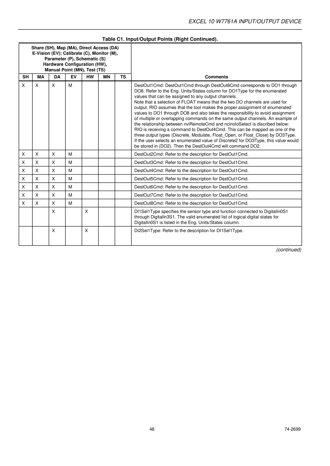
Table C1. Input/Output Points (Right Continued).
Share (SH), Map (MA), Direct Access (DA)
Parameter (P), Schematic (S)
Hardware Configuration (HW),
Manual Point (MN), Test (TS)
SH | MA | DA | EV | HW | MN | TS | Comments |
|
|
|
|
|
|
|
|
X | X | X | M |
|
|
| DestOut1Cmd: DestOut1Cmd through DestOut8Cmd corresponds to DO1 through |
|
|
|
|
|
|
| DO8. Refer to the Eng. Units/States column for DO1Type for the enumerated |
|
|
|
|
|
|
| values that can be assigned to any output channels. |
|
|
|
|
|
|
| Note that a selection of FLOAT means that the two DO channels are used for |
|
|
|
|
|
|
| output. RIO assumes that the tool makes the proper assignment of enumerated |
|
|
|
|
|
|
| values to DO1 through DO8 and also takes the responsibility to avoid assignment |
|
|
|
|
|
|
| of multiple or overlapping commands on the same output channels. An example of |
|
|
|
|
|
|
| the relationship between nviRemoteCmd and ncirioIoSelect is discribed below: |
|
|
|
|
|
|
| RIO is receiving a command to DestOut4Cmd. This can be mapped as one of the |
|
|
|
|
|
|
| three output types (Discrete, Modulate, Float_Open, or Float_Close) by DO3Type. |
|
|
|
|
|
|
| If the user selects an enumerated value of Discrete2 for DO3Type, this value would |
|
|
|
|
|
|
| be stored in (DO2). Then the DestOut4Cmd will command DO2. |
|
|
|
|
|
|
|
|
X | X | X | M |
|
|
| DestOut2Cmd: Refer to the description for DestOut1Cmd. |
|
|
|
|
|
|
|
|
X | X | X | M |
|
|
| DestOut3Cmd: Refer to the description for DestOut1Cmd. |
|
|
|
|
|
|
|
|
X | X | X | M |
|
|
| DestOut4Cmd: Refer to the description for DestOut1Cmd. |
|
|
|
|
|
|
|
|
X | X | X | M |
|
|
| DestOut5Cmd: Refer to the description for DestOut1Cmd. |
|
|
|
|
|
|
|
|
X | X | X | M |
|
|
| DestOut6Cmd: Refer to the description for DestOut1Cmd. |
|
|
|
|
|
|
|
|
X | X | X | M |
|
|
| DestOut7Cmd: Refer to the description for DestOut1Cmd. |
|
|
|
|
|
|
|
|
X | X | X | M |
|
|
| DestOut8Cmd: Refer to the description for DestOut1Cmd. |
|
|
|
|
|
|
|
|
|
| X |
| X |
|
| DI1Sel1Type specifies the sensor type and function connected to DigitalIn0S1 |
|
|
|
|
|
|
| through DigitalIn3S1. The valid enumerated list of logical digital states for |
|
|
|
|
|
|
| DigitalIn0S1 is listed in the Eng. Units/States column. |
|
|
|
|
|
|
|
|
|
| X |
| X |
|
| DI2Sel1Type: Refer to the description for DI1Sel1Type. |
|
|
|
|
|
|
|
|
(continued)
48 |
