KM-320MAH, MRH KM-600MAH KM-650MAH, MWH(-M), MRH KM-901MAH, MRH/3 specifications
Hoshizaki, a leading manufacturer in the food service equipment sector, offers a diverse range of ice-making machines that excel in efficiency, durability, and innovative technology. Among the notable models are the Hoshizaki MWH KM-515MAH, MWH(-M), MRH KM-901MAH, MRH KM-600MAH, KM-650MAH, and KM-320MAH. Each model brings unique features designed to meet varying commercial ice production needs.The Hoshizaki MWH KM-515MAH is particularly recognized for its high ice production capacity, generating up to 515 pounds of ice per day. This model incorporates advanced technology that ensures consistent ice quality and purity. The MWH(-M) variant often includes modifications to suit specific operational environments, ensuring reliability in diverse settings.
Similarly, the MRH KM-901MAH stands out with its ability to produce a staggering 901 pounds of ice per day, making it ideal for high-volume establishments. This model is equipped with Hoshizaki's unique "cubelet" technology, producing a soft, chewable ice perfect for beverages. It also features a robust stainless steel construction, enhancing its durability and resistance to corrosion.
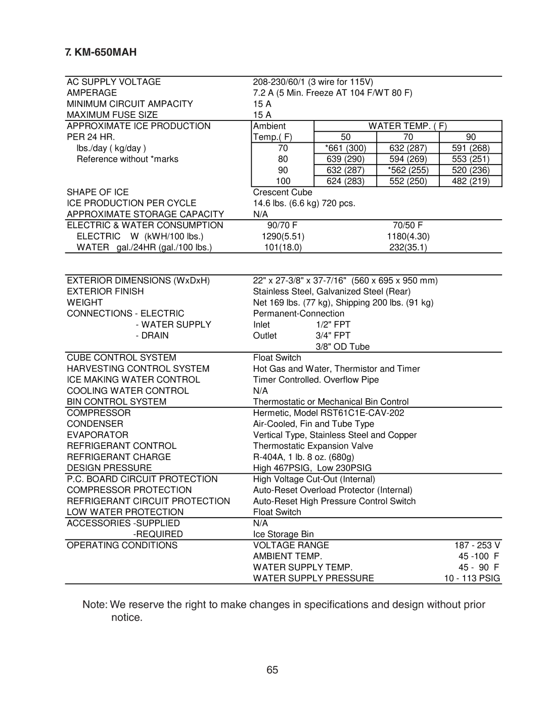
The MRH KM-600MAH offers 600 pounds of daily ice output, while the KM-650MAH enhances that capacity to 650 pounds. Both machines prioritize energy efficiency and come with built-in energy-saving modes. These models feature advanced ice sensing technology that monitors production levels to optimize energy consumption and reduce waste.
On the other hand, the KM-320MAH is designed for smaller establishments, with a daily ice production rate of 320 pounds. Despite its smaller footprint, it maintains high production efficiency and is equipped with features like a built-in storage bin, saving space while ensuring a reliable ice supply.
Across these models, Hoshizaki employs various technologies, including air-cooled and water-cooled systems, offering flexibility depending on installation requirements. The ice machines are designed with user-friendly controls and features like self-cleaning capabilities, making maintenance straightforward and less time-consuming.
In summary, Hoshizaki's ice machines, including the MWH KM-515MAH, MRH KM-901MAH, and others, deliver exceptional ice production, durability, and efficiency tailored to meet the demands of any commercial kitchen or service establishment. With a commitment to quality, Hoshizaki continues to be a trusted choice for businesses needing reliable ice-making solutions.