Removal and Replacement Procedures
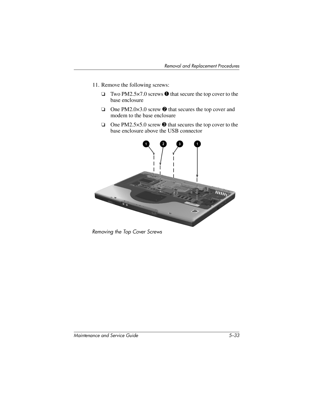
11.Remove the following screws:
❏Two PM2.5×7.0 screws 1 that secure the top cover to the base enclosure
❏One PM2.0×3.0 screw 2 that secures the top cover and modem to the base enclosure
❏One PM2.5×5.0 screw 3 that secures the top cover to the base enclosure above the USB connector
Removing the Top Cover Screws
Maintenance and Service Guide |
