Removal and Replacement Procedures
5.1 Serial Number
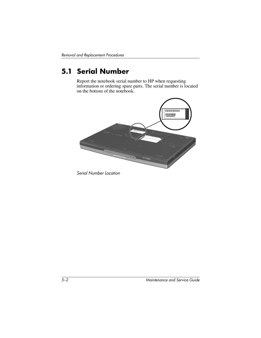
Report the notebook serial number to HP when requesting information or ordering spare parts. The serial number is located on the bottom of the notebook.
Serial Number Location
Maintenance and Service Guide |