Removal and Replacement Procedures
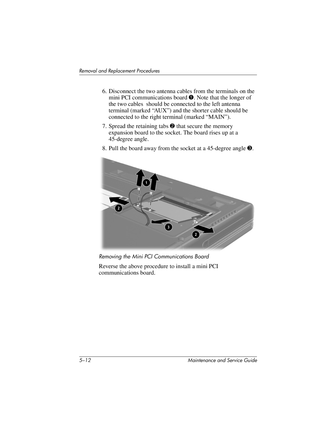
6.Disconnect the two antenna cables from the terminals on the mini PCI communications board 1. Note that the longer of the two cables should be connected to the left antenna terminal (marked “AUX”) and the shorter cable should be connected to the right terminal (marked “MAIN”).
7.Spread the retaining tabs 2 that secure the memory expansion board to the socket. The board rises up at a
8.Pull the board away from the socket at a
Removing the Mini PCI Communications Board
Reverse the above procedure to install a mini PCI communications board.
Maintenance and Service Guide |
