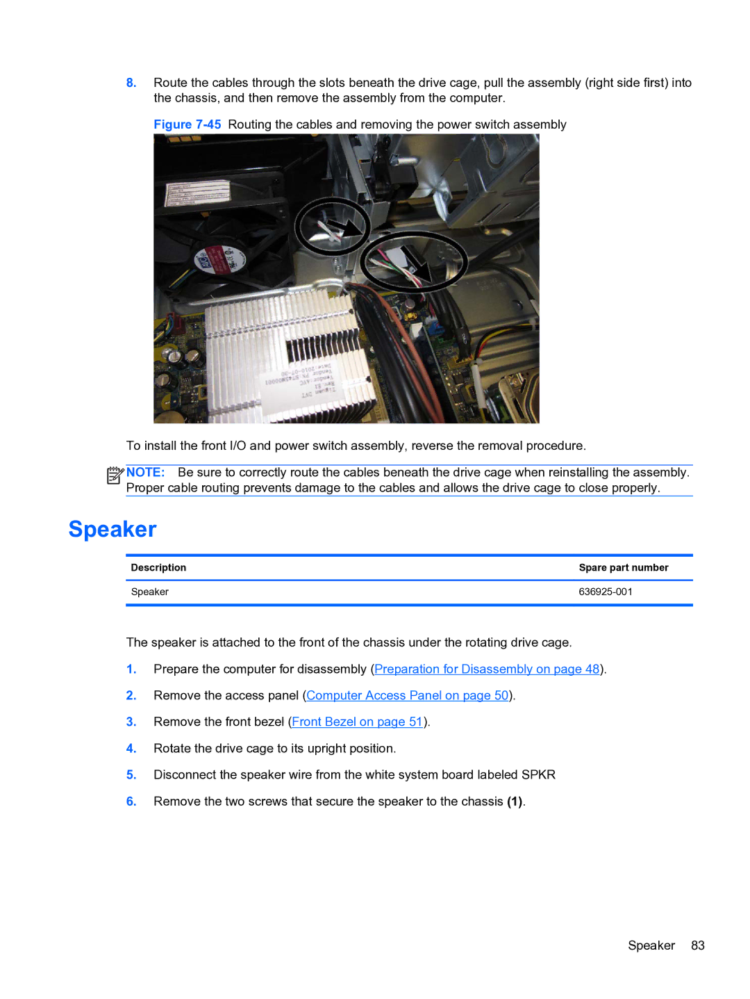
8.Route the cables through the slots beneath the drive cage, pull the assembly (right side first) into the chassis, and then remove the assembly from the computer.
Figure 7-45 Routing the cables and removing the power switch assembly
To install the front I/O and power switch assembly, reverse the removal procedure.
![]()
![]()
![]()
![]() NOTE: Be sure to correctly route the cables beneath the drive cage when reinstalling the assembly. Proper cable routing prevents damage to the cables and allows the drive cage to close properly.
NOTE: Be sure to correctly route the cables beneath the drive cage when reinstalling the assembly. Proper cable routing prevents damage to the cables and allows the drive cage to close properly.
Speaker
Description | Spare part number |
|
|
Speaker |
|
|
|
The speaker is attached to the front of the chassis under the rotating drive cage.
1.Prepare the computer for disassembly (Preparation for Disassembly on page 48).
2.Remove the access panel (Computer Access Panel on page 50).
3.Remove the front bezel (Front Bezel on page 51).
4.Rotate the drive cage to its upright position.
5.Disconnect the speaker wire from the white system board labeled SPKR
6.Remove the two screws that secure the speaker to the chassis (1).
Speaker 83