EM78P447N
8-Bit Microcontroller with OTP ROM
(A)Any of the wake-up pins is “0” as illustrated in Figure. 5. Upon waking, the controller will continue to execute the succeeding address. Under this case, before entering SLEEP2 MODE, the wake-up function of the trigger sources (P60~P67 and P74~P75) should be selected (e.g., input pin) and enabled (e.g., pull-high, wake-up control). It should be noted that after waking up, the WDT is enabled if the Code Option bit ENWDT is “0”. The WDT operation (to be enabled or disabled) should be appropriately controlled by software after waking up.
(B)WDT time-out (if enabled) or external reset input on /RESET pin will trigger a controller reset.
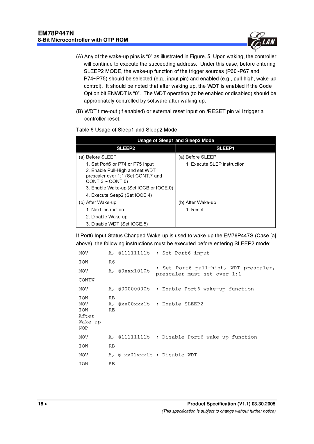
Table 6 Usage of Sleep1 and Sleep2 Mode
Usage of Sleep1 and Sleep2 Mode
(a) Before SLEEP | (a) Before SLEEP |
1. | Set Port6 or P74 or P75 Input | 1. Execute SLEP instruction |
2. | Enable Pull-High and set WDT | |
prescaler over 1:1 (Set CONT.7 and | |
CONT.3 ~ CONT.0) | |
3. | Enable Wake-up (Set IOCB or IOCE.0) | |
4. | Execute Seep2 (Set IOCE.4) | |
(b) After Wake-up | (b) After Wake-up |
1. | Next instruction | 1. Reset |
2. | Disable Wake-up | |
3. | Disable WDT (Set IOCE.5) | |
If Port6 Input Status Changed Wake-up is used to wake-up the EM78P447S (Case [a] above), the following instructions must be executed before entering SLEEP2 mode:
MOV | A, @11111111b |
IOW | R6 |
MOV | A, @0xxx1010b |
CONTW | |
;Set Port6 input
;Set Port6 pull-high, WDT prescaler, prescaler must set over 1:1
MOV | A, @00000000b | ; Enable Port6 wake-up function |
IOW | RB | ; Enable SLEEP2 |
MOV | A, @xx00xxx1b |
IOW | RE | |
After | | |
Wake-up | | |
NOP | | |
MOV | A, @11111111b | ; Disable Port6 wake-up function |
IOW | RB | |
MOV | A, @ xx01xxx1b | ; Disable WDT |
IOW | RE | |
18 • | Product Specification (V1.1) 03.30.2005 |
(This specification is subject to change without further notice)

