EM78P447N
4.13 Timing Diagram
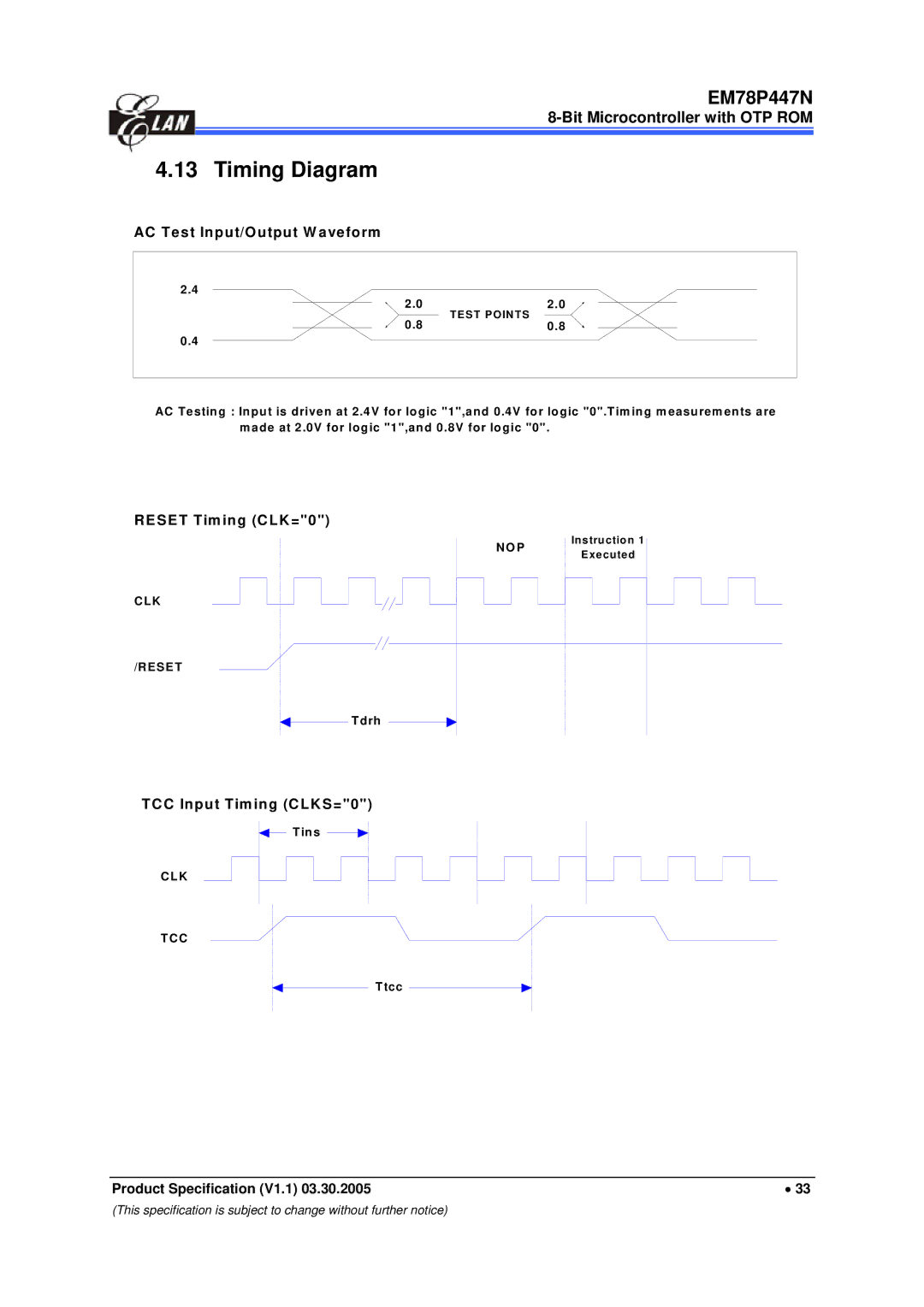
AC Test Input/Output W aveform
2.4 |
|
2.0 | 2.0 |
0.8 | TEST POINTS |
0.8 | |
0.4 |
|
AC Testing : Input is driven at 2.4V for logic "1",and 0.4V for logic "0".Tim ing measurements are made at 2.0V for logic "1",and 0.8V for logic "0".
RESET Timing (CLK="0")
N O P | Instruction 1 | |
Executed | ||
|
C LK
/RESET
T drh
TCC Input Timing (CLKS="0")
T ins
C LK
TC C
Ttcc
Product Specification (V1.1) 03.30.2005 | • 33 |
(This specification is subject to change without further notice)