EM78P447N
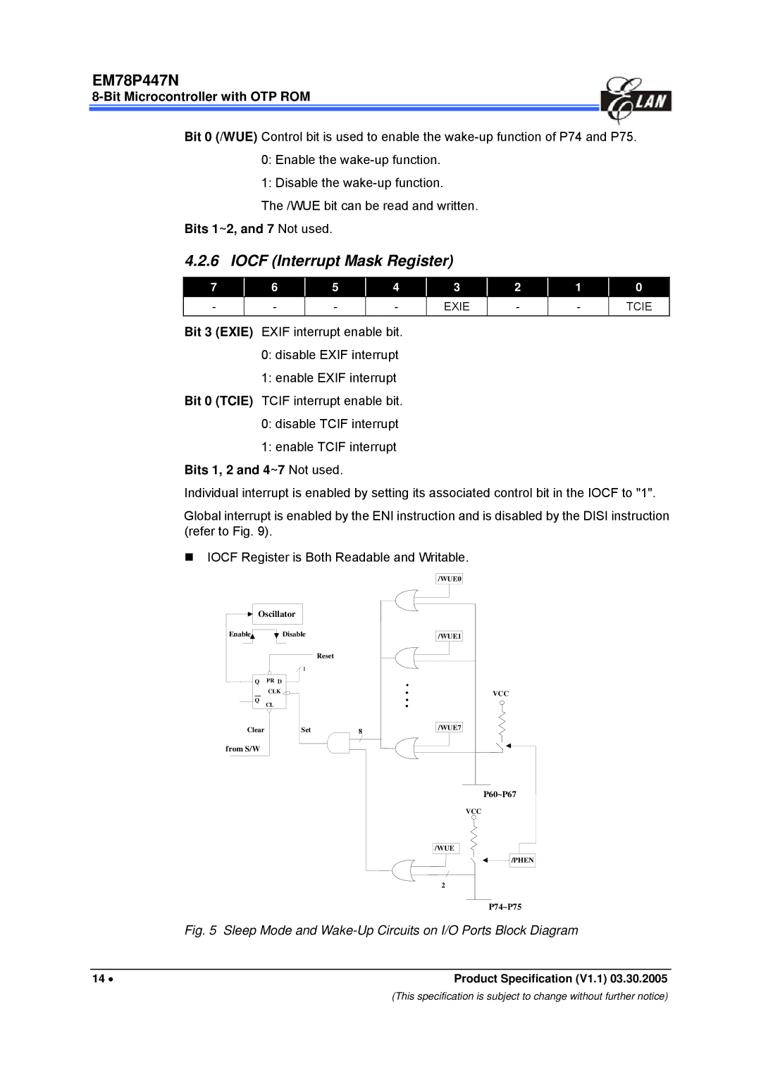
Bit 0 (/WUE) Control bit is used to enable the
0:Enable the
1:Disable the
The /WUE bit can be read and written.
Bits 1~2, and 7 Not used.
4.2.6 IOCF (Interrupt Mask Register)
7 |
| 6 |
| 5 |
| 4 |
|
- |
| - |
| - |
| - |
|
|
|
|
|
|
|
|
|
3
EXIE
| 2 |
| 1 |
| 0 |
| - |
| - |
| TCIE |
|
|
|
|
|
|
Bit 3 (EXIE) EXIF interrupt enable bit.
0:disable EXIF interrupt
1:enable EXIF interrupt Bit 0 (TCIE) TCIF interrupt enable bit.
0:disable TCIF interrupt
1:enable TCIF interrupt
Bits 1, 2 and 4~7 Not used.
Individual interrupt is enabled by setting its associated control bit in the IOCF to "1".
Global interrupt is enabled by the ENI instruction and is disabled by the DISI instruction (refer to Fig. 9).
IOCF Register is Both Readable and Writable.
|
|
| /WUE0 |
Oscillator |
|
| |
Enable | Disable |
| /WUE1 |
|
| Reset |
|
Q | PR D |
|
|
Q | CLK |
| VCC |
CL |
|
| |
Clear | Set | 8 | /WUE7 |
from S/W
P60~P67
VCC
/WUE
/PHEN
2
P74~P75
Fig. 5 Sleep Mode and Wake-Up Circuits on I/O Ports Block Diagram
14 • | Product Specification (V1.1) 03.30.2005 |
(This specification is subject to change without further notice)
