EM78P447N
Bit 4 (TE) TCC signal edge
0:increment if the transition from low to high takes place on TCC pin
1:increment if the transition from high to low takes place on TCC pin
Bit 3 (PAB) Prescaler assignment bit.
0:TCC
1:WDT
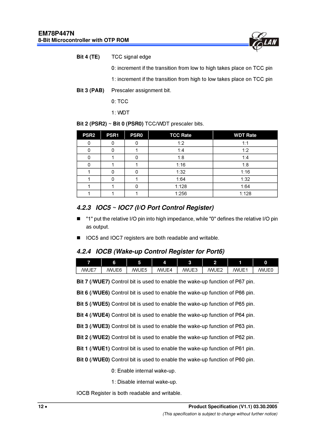
Bit 2 (PSR2) ~ Bit 0 (PSR0) TCC/WDT prescaler bits.
PSR2 |
| PSR1 |
| PSR0 |
| TCC Rate |
|
0 |
| 0 |
| 0 |
| 1:2 |
|
0 |
| 0 |
| 1 |
| 1:4 |
|
0 |
| 1 |
| 0 |
| 1:8 |
|
0 |
| 1 |
| 1 |
| 1:16 |
|
1 |
| 0 |
| 0 |
| 1:32 |
|
1 |
| 0 |
| 1 |
| 1:64 |
|
1 |
| 1 |
| 0 |
| 1:128 |
|
1 |
| 1 |
| 1 |
| 1:256 |
|
WDT Rate
1:1
1:2
1:4
1:8
1:16
1:32
1:64
1:128
4.2.3 IOC5 ~ IOC7 (I/O Port Control Register)
"1" put the relative I/O pin into high impedance, while "0" defines the relative I/O pin as output.
IOC5 and IOC7 registers are both readable and writable.
4.2.4 IOCB (Wake-up Control Register for Port6)
7 |
| 6 |
| 5 |
| 4 |
| 3 |
| 2 |
| 1 |
| 0 |
|
/WUE7 |
| /WUE6 |
| /WUE5 |
| /WUE4 |
| /WUE3 |
| /WUE2 |
| /WUE1 |
| /WUE0 |
|
Bit 7 (/WUE7) Control bit is used to enable the
Bit 6 (/WUE6) Control bit is used to enable the
Bit 5 (/WUE5) Control bit is used to enable the
Bit 4 (/WUE4) Control bit is used to enable the
Bit 3 (/WUE3) Control bit is used to enable the
Bit 2 (/WUE2) Control bit is used to enable the
Bit 1 (/WUE1) Control bit is used to enable the
Bit 0 (/WUE0) Control bit is used to enable the
0:Enable internal
1:Disable internal
IOCB Register is both readable and writable.
12 • | Product Specification (V1.1) 03.30.2005 |
(This specification is subject to change without further notice)
