|
|
|
|
|
|
| 8086 |
|
|
| Table 1. Pin Description (Continued) |
| |||
|
|
|
|
|
|
| |
Symbol | Pin No. | Type |
|
| Name and Function | ||
|
|
|
|
|
| ||
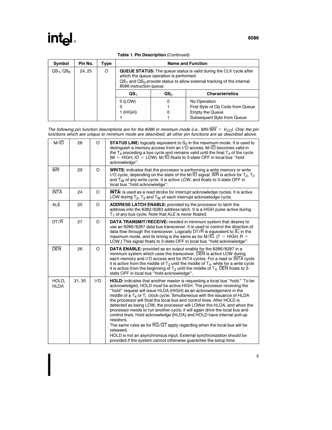
QS1, QS0 | 24, 25 | O | QUEUE STATUS: The queue status is valid during the CLK cycle after | ||||
|
|
| which the queue operation is performed. | ||||
|
|
| QS1 and QS0 provide status to allow external tracking of the internal | ||||
|
|
| 8086 instruction queue. |
| |||
|
|
|
|
|
|
|
|
|
|
|
| QS1 | QS0 |
| Characteristics |
|
|
| 0 | (LOW) | 0 |
| No Operation |
|
|
| 0 |
| 1 |
| First Byte of Op Code from Queue |
|
|
| 1 | (HIGH) | 0 |
| Empty the Queue |
|
|
| 1 |
| 1 |
| Subsequent Byte from Queue |
|
|
|
|
|
|
|
|
The following pin function descriptions are for the 8086 in minimum mode (i.e., MN/MX e VCC). Only the pin functions which are unique to minimum mode are described; all other pin functions are as described above.
|
|
|
|
|
|
|
|
|
|
|
|
|
|
|
|
|
| M/IO | 28 | O | STATUS LINE: logically equivalent to S2 in the maximum mode. It is used to | ||||||||||||
|
|
|
|
|
|
|
|
|
| distinguish a memory access from an I/O access. M/IO becomes valid in | ||||||
|
|
|
|
|
|
|
|
|
| the T4 preceding a bus cycle and remains valid until the final T4 of the cycle | ||||||
|
|
|
|
|
|
|
|
|
| (M e HIGH, IO e LOW). M/IO floats to | ||||||
|
|
|
|
|
|
|
|
|
| acknowledge’’. | ||||||
|
|
|
|
|
|
|
|
|
|
|
|
|
|
|
| |
|
|
|
|
|
|
|
|
|
|
|
|
|
|
|
| |
| WR | 29 | O | WRITE: indicates that the processor is performing a write memory or write | ||||||||||||
|
|
|
|
|
|
|
|
|
| I/O cycle, depending on the state of the M/IO signal. WR is active for T2, T3 | ||||||
|
|
|
|
|
|
|
|
|
| and TW of any write cycle. It is active LOW, and floats to | ||||||
|
|
|
|
|
|
|
|
|
| local bus ‘‘hold acknowledge’’. | ||||||
|
|
|
|
|
|
|
|
|
|
|
|
|
|
| ||
|
|
|
|
|
|
|
|
|
|
|
|
|
|
| ||
| INTA | 24 | O | INTA: is used as a read strobe for interrupt acknowledge cycles. It is active | ||||||||||||
|
|
|
|
|
|
|
|
|
| LOW during T2, T3 and TW of each interrupt acknowledge cycle. | ||||||
| ALE | 25 | O | ADDRESS LATCH ENABLE: provided by the processor to latch the | ||||||||||||
|
|
|
|
|
|
|
|
|
| address into the 8282/8283 address latch. It is a HIGH pulse active during | ||||||
|
|
|
|
|
|
|
|
|
| T1 of any bus cycle. Note that ALE is never floated. | ||||||
|
|
|
|
|
|
|
|
|
|
|
| |||||
| DT/R | 27 | O | DATA TRANSMIT/RECEIVE: needed in minimum system that desires to | ||||||||||||
|
|
|
|
|
|
|
|
|
| use an 8286/8287 data bus transceiver. It is used to control the direction of | ||||||
|
|
|
|
|
|
|
|
|
| data flow through the transceiver. Logically DT/R is equivalent to S1 in the | ||||||
|
|
|
|
|
|
|
|
|
| maximum mode, and its timing is the same as for M/IO. (T e HIGH, R e | ||||||
|
|
|
|
|
|
|
|
|
| LOW.) This signal floats to | ||||||
|
|
|
|
|
|
|
|
|
| |||||||
|
|
|
|
|
|
|
|
|
| |||||||
| DEN | 26 | O | DATA ENABLE: provided as an output enable for the 8286/8287 in a | ||||||||||||
|
|
|
|
|
|
|
|
|
| minimum system which uses the transceiver. DEN is active LOW during | ||||||
|
|
|
|
|
|
|
|
|
| each memory and I/O access and for INTA cycles. For a read or INTA cycle | ||||||
|
|
|
|
|
|
|
|
|
| it is active from the middle of T2 until the middle of T4, while for a write cycle | ||||||
|
|
|
|
|
|
|
|
|
| it is active from the beginning of T2 until the middle of T4. DEN floats to 3- | ||||||
|
|
|
|
|
|
|
|
|
| state OFF in local bus ‘‘hold acknowledge’’. | ||||||
|
|
|
|
|
|
|
|
| ||||||||
| HOLD, | 31, 30 | I/O | HOLD: indicates that another master is requesting a local bus ‘‘hold.’’ To be | ||||||||||||
| HLDA |
|
| acknowledged, HOLD must be active HIGH. The processor receiving the | ||||||||||||
|
|
|
|
|
|
|
|
|
| ‘‘hold’’ request will issue HLDA (HIGH) as an acknowledgement in the | ||||||
|
|
|
|
|
|
|
|
|
| middle of a T4 or Ti clock cycle. Simultaneous with the issuance of HLDA | ||||||
|
|
|
|
|
|
|
|
|
| the processor will float the local bus and control lines. After HOLD is | ||||||
|
|
|
|
|
|
|
|
|
| detected as being LOW, the processor will LOWer the HLDA, and when the | ||||||
|
|
|
|
|
|
|
|
|
| processor needs to run another cycle, it will again drive the local bus and | ||||||
|
|
|
|
|
|
|
|
|
| control lines. Hold acknowledge (HLDA) and HOLD have internal | ||||||
|
|
|
|
|
|
|
|
|
| resistors. | ||||||
|
|
|
|
|
|
|
|
|
|
|
|
|
|
| ||
|
|
|
|
|
|
|
|
|
| The same rules as for RQ/GT apply regarding when the local bus will be | ||||||
|
|
|
|
|
|
|
|
|
| released. | ||||||
|
|
|
|
|
|
|
|
|
| HOLD is not an asynchronous input. External synchronization should be | ||||||
|
|
|
|
|
|
|
|
|
| provided if the system cannot otherwise guarantee the setup time. | ||||||
|
|
|
|
|
|
|
|
|
|
|
|
|
|
|
|
|
5