RMX/SO |
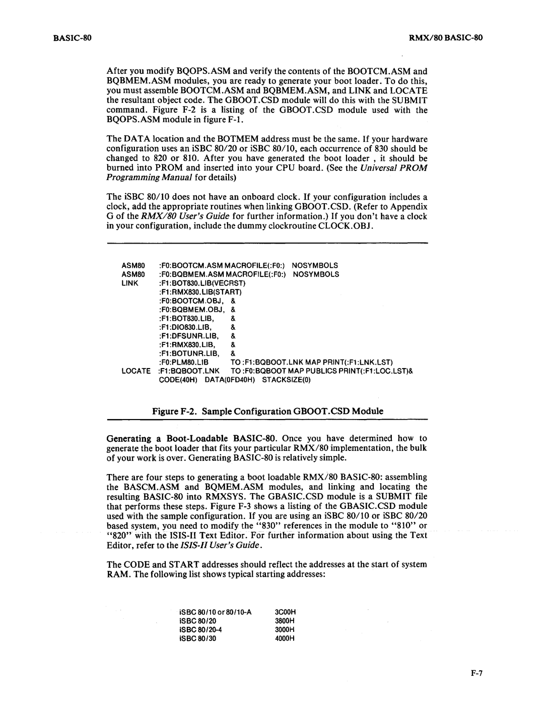
After you modify BQOPS.ASM and verify the contents of the BOOTCM.ASM and BQBMEM.ASM modules, you are ready to generate your boot loader. To do this, you must assemble BOOTCM.ASM and BQBMEM.ASM, and LINK and LOCATE the resultant object code. The GBOOT.CSD module will do this with the SUBMIT command. Figure
The DATA location and the BOTMEM address must be the same. If your hardware configuration uses an iSBC SO/20 or iSBC S0/10, each occurrence of S30 should be changed to S20 or SID. After you have generated the boot loader, it should be burned into PROM and inserted into your CPU board. (See the Universal PROM Programming Manual for details)
The iSBC SO/10 does not have an onboard clock. If your configuration includes a clock, add the appropriate routines when linking GBOOT.CSD. (Refer to Appendix G of the RMX/80 User's Guide for further information.) If you don't have a clock in your configuration, include the dummy clockroutine CLOCK.OBJ.
ASM80 | :FO:BOOTCM.ASM MACROFILE(:FO:) | NOSYMBOLS | |
ASM80 | :FO:BQBMEM.ASM MACROFILE(:FO:) | NOSYMBOLS | |
LINK | :F1 :BOT830.LlB(VECRST) |
| |
| :F1 :RMX830.LlB(START) |
| |
| :FO:BOOTCM.OBJ, | & |
|
| :FO:BQBMEM.OBJ, | & |
|
| :F1 :BOT830. LIB, | & |
|
| :F1 :DI0830.LlB, | & |
|
| :F1 :DFSUNR.LlB, | & |
|
| :F1 :RMX830.LlB, | & |
|
| :F1 :BOTUNR.LlB, | & |
|
| :FO:PLM80.LlB | TO :F1:BQBOOT.LNK MAP PRINT(:F1:LNK.LST) | |
LOCATE :F1 :BQ800T.LNK TO :FO:BQBOOT MAP PUBLICS PRINT(:F1 :LOC.LST)& CODE(40H) DATA(OFD40H) STACKSIZE(O)
Figure F-2. Sample Configuration OBOOT.CSD Module
Generating a Boot-Loadable BASIC-80. Once you have determined how to generate the boot loader that fits your particular RMX/SO implementation, the bulk of your work is over. Generating BASIC-SO is relatively simple.
There are four steps to generating a boot loadable RMX/80 BASIC-80: assembling the BASCM.ASM and BQMEM.ASM modules, and linking and locating the resulting BASIC-SO into RMXSYS. The GBASIC.CSD module is a SUBMIT file that performs these steps. Figure F-3 shows a listing of the GBASIC.CSD module used with the sample configuration. If you are using an iSBC 80/10 or iSBC SO/20 based system, you need to modify the "S30" references in the module to "SI0" or "S20" with the ISIS-II Text Editor. For further information about using the Text Editor, refer to the ISIS-II User's Guide.
The CODE and START addresses should reflect the addresses at the start of system RAM. The following list shows typical starting addresses:
3COOH | |
iSBC 80/20 | 3800H |
iSBC | 3000H |
iSBC 80/30 | 4000H |
