BASIC-SO Reference Manual
A108/0979/7500 FL
Preface
Page
Contents
Illustrations
Invoking BASIC-80
Chapter Introduction to BASIC-80
Filename
Examples
Introduction to BASIC-80
Basic filename MEMTOPaddress
Deleting a File
Listing the Directory of a Disk
Renaming a File
Changing File Attributes
Save LP ,A
You can now run, list, or edit the program
Statements
Commands
BASIC-80 Statements
BASIC-80 Commands Contd
BASIC-80 Functions
BASIC-80 Statements Contd
BASIC-80 Functions Contd
Functions
Representing Data
Hexadecimal Integer Constants
Constants
Integer Constants
Decimal Integer Constants
Double-Precision Floating-Point Constants
Octal Integer Constants
Single-Precision Floating-Point Constants
$ = Enter next data string
String Constants
String Variables
This is a string constant
YI,1
L4! = Csng l4
String Arrays
BASIC-SO Operators in Order of Precedence Contd
Arithmetic Operators
String Expressions
Logical Operators
String Operator
Numeric Expressions
Entering and Editing Programs
30 A--=8xx*522537 Control-R a = 8*37
30 A=8*52
30 A=8
30 A=8*52 30 A=8*37
If AB then
Subcommand
Command 3D press 3, then D results
Integer D
If AB then 120 Else Null SET
At this point, the other editing subcommands may be used
Syntax of the X subcommand is
Print Undefined SET. Enter a L
Print Undefined SET The E subcommand is entered
Integer C character character
Move the cursor to PRINT. Enter 2C RE L
Overflow, Underflow, and Divide-by-Zero
BASIC-80 Error Messages
Syntax Error Messages
Error Trapping
Trace Facility
If line 40 is replaced with
Error Simulation
Error Handling
Restarting Program Execution
Open 1,#1,F1DATES
Opening a Sequential File
If executed four times, it would read all eight values
Refer to for further details of Print Using
Writing to a Sequential File
Reading from a Sequential File
Value of R$ would be
Closing a Sequential File
Field #3, 20 AS N$
Buffers
Defining a Random 1/0 Field-FIELD
Field #3, 20 AS N$, 9 AS SS$
Disk File Input/Output
To read the next record
Opening and Closing a Random Disk File
Reading from a Random 1/0 File
Any of the parameters can be variables
Double-precision value
Writing to a Random 1/0 File
Integer
Single-precision value
MKI$
Clear expression,address
Attrib Fdrive numberfilename, W1
Attrib Fdrive numberfilename, WO
Auto first lineJ, increment
Close
Commands and Statements
Rules for function name are the same as for variable name
DEF FNX
Defsng Defdbl Defstr Defint
Delete
DIM
END
Error
DIR
Edit
FOR-NEXT-STEP
Error expression
Exit
Field
GET I file number ,record number
GET
Gosub
For variable=expression to expression Step expression
Goto
IF-THEN-ELSE
Input
List
Kill
LET
Line Input
Load
LSET, Rset
NEW
Merge
9 16
Next
Open
On ... Gosub
On ... Goto
Poke
Option Base
OUT
String Fields
Print Using
Print
If X$=SEVEN and Y$=EIGHT, the results of line 40 would be
Numeric fields
PUT
Prun
Read
Randomize
REM
Return
Resume
60 END
Save
RUN line numberlstring expression ,F
Line number RUN filename
? 5,8,2
TRON, Troff
Width
Wait
ATN
ABS
Functions
CHR$
Cint
AO/o =
Csng
CVI CVS
10 A# = 1.00/3.00
EOF
Dskf
Ok·
FIX
Inputs
Hexs
INP
LEFT$
INT
Instr
LOG
LEN
LOC
LOF
OCT$
MID$
MKI$ MKS$ MKD$
RIGHT$ string,integer
Rights
Peek expression
POS integer
10 a =1
SGN
SIN
Spaces
SQRexpression
SPC
SPC integer
If A$ = 2 then Print Correct Else Goto
TAN expression
STR$ expression
TAB expression
60 AO/o =
Here is an example of how the USRn statement is used
Table A-I. BASIC-80 Error Codes
Appendix a BASIC-SO Error Codes
Table A-I. BASIC-SO Error Codes Contd
Appendix B BASIC-SO Reserved Words
Page
To resume program execution after it is stopped by
To halt program execution and return to command
Level
To tab across the line
Page
Appendix D Ascii Codes
Table D-l. Ascii Code List
BEL
Table D-2. Ascii Code Definition
Appendixe
Calling Subroutines
Figure B-1. Internal Representation of Numbers and Strings
RESULT=USR%1VARPTRA, VARPTRB, VARPTRC» PRINTA+B+C= Result
Some Real Examples
Figure E-2 /8085 Assembly Language Program
Figure E-3. PL/M-80 Program
Appendix F RMX/SO BASIC-SO
ISIS-II BASIC-SO
Initializing the Predefined RMX/SO BASIC-SO Configuration
OOOOH-OFFFH
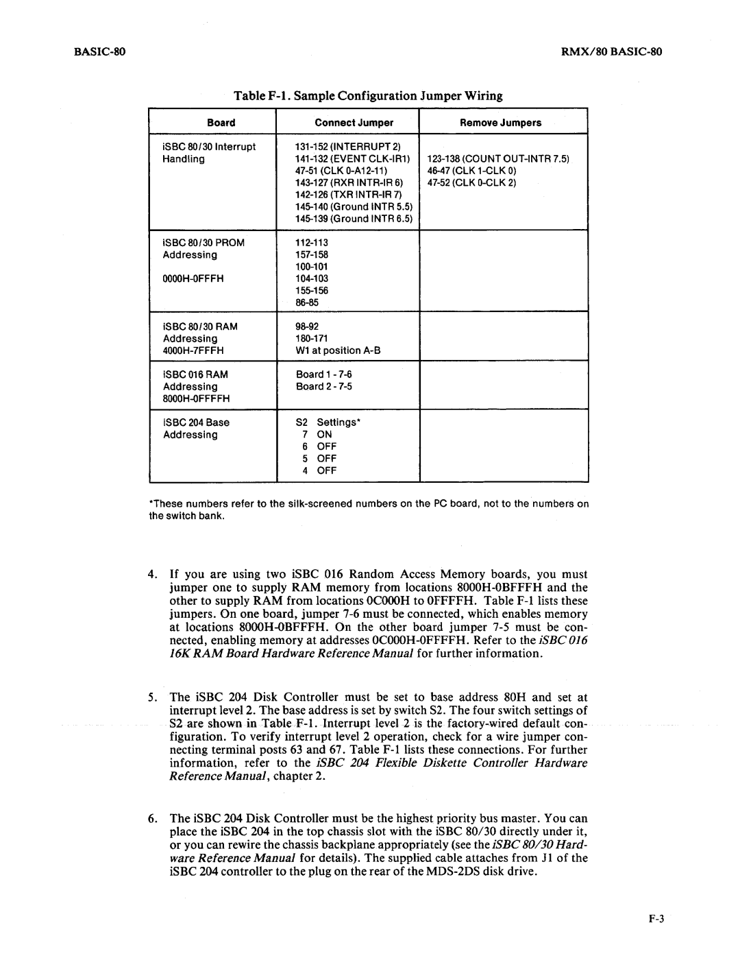
Table F-l. Sample Configuration Jumper Wiring
BASIC-80 Executable Files
Generating Boot-Loaded and PROM-Based Versions
BASIC-80 Source Files
BASIC-80 Object Files
Generating a Boot-Loaded RMX/80 BASIC-80
This option enables your user-written I/O drivers if you
That are not boot loaded
This option is used to allocate memory. It is 1 if the boot
Setting baud rates, refer to the RMX/SO Users Guide
ISBC 80/20-4
Generating a PROM-Based RMX/80 BASIC-80
Prom
F1 RMX820.L1BSTART, & FOBASCM.OBJ,& FORMXBAS.LlB
F1 DFSDIR. L1BDIRECTORY ,RENAM E,& F1 MTI810.L1B
ISBC SO/10 System Clock
Configuring DFS on an iSBC 80/10
Adding BASIC-SO to an Existing RMX/SO Configuration
Configuration Requirements
Public Variables
Open 0,#1, L1LlST
Adding User-Written I/O Drivers to RMX/SO BASIC-SO
Figure F-S. Sample User-Written 1/0 Driver Routine
Burning a BASIC-80 Program Into Prom
Altering BASIC-80 Workspace
Baprom F1HEATER.BAS
Page
Index
Ase
BASIC-80
RIGHT$,7-1O
Request for Readerscomments
111111