Chapter 2. Installing the KZPCM Host Adapter
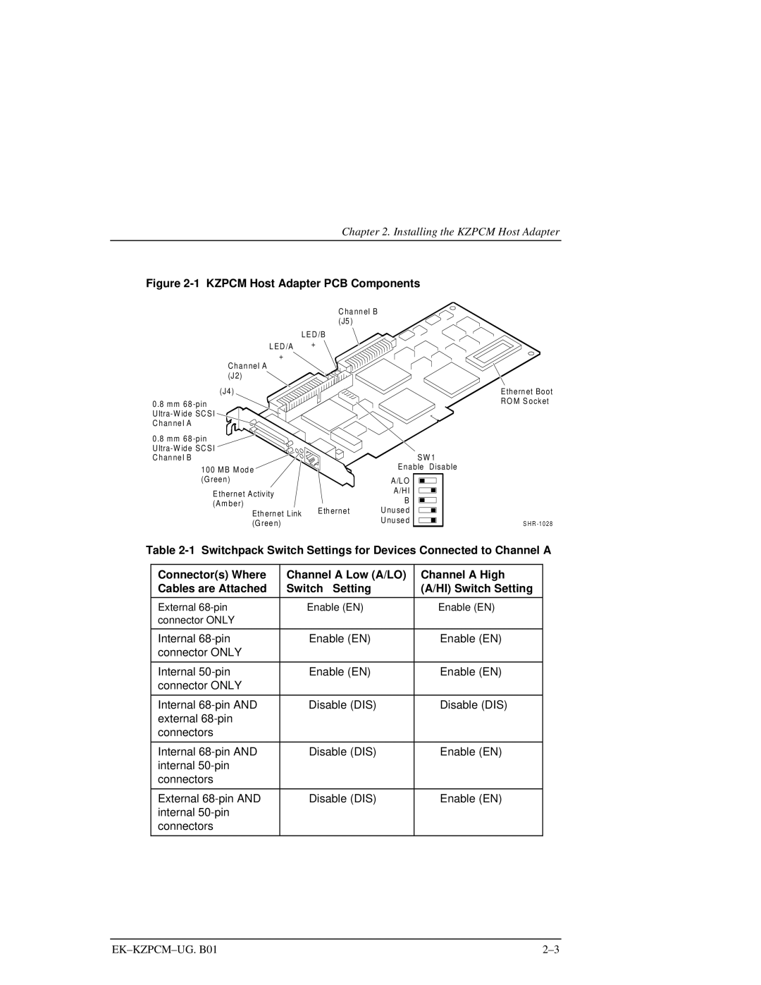
Figure 2-1 KZPCM Host Adapter PCB Components
C ha nn el B (J5 )
LED /B
L ED /A +
+
Chan nel A![]() (J2)
(J2) ![]()
![]()
![]()
![]()
![]()
![]()
![]()
(J4) |
| |
0.8 mm 68 |
| |
U |
| |
C han ne l A |
| |
0.8 mm 68 |
| |
U |
| |
C han ne l B |
| |
100 MB M od e |
| |
(Green) |
| |
E thernet Activity |
| |
(Am ber) | Eth ernet | |
Eth ern et Link | ||
| ||
(Gree n) |
|
SW 1
Enable Disable
A/L O
A/HI
B
U nu se d
U nu se d
Ethern et Boot RO M S ocket
S H R
Table
Connector(s) Where | Channel A Low (A/LO) | Channel A High |
Cables are Attached | Switch Setting | (A/HI) Switch Setting |
|
|
|
External | Enable (EN) | Enable (EN) |
connector ONLY |
|
|
|
|
|
Internal | Enable (EN) | Enable (EN) |
connector ONLY |
|
|
|
|
|
Internal | Enable (EN) | Enable (EN) |
connector ONLY |
|
|
|
|
|
Internal | Disable (DIS) | Disable (DIS) |
external |
|
|
connectors |
|
|
|
|
|
Internal | Disable (DIS) | Enable (EN) |
internal |
|
|
connectors |
|
|
|
|
|
External | Disable (DIS) | Enable (EN) |
internal |
|
|
connectors |
|
|
|
|
|
