Controls, Connectors, and Indicators
Front Panel
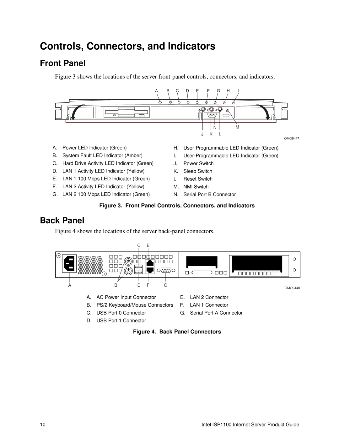
Figure 3 shows the locations of the server front-panel controls, connectors, and indicators.
A B C D E F G H I
| N | M |
J | K | L |
OMO9447
A. | Power LED Indicator (Green) | H. | ||
B. | System Fault LED Indicator (Amber) | I. | ||
C. | Hard Drive Activity LED Indicator (Green) | J. | Power Switch | |
D. | LAN 1 | Activity LED Indicator (Yellow) | K. | Sleep Switch |
E. | LAN 1 | 100 Mbps LED Indicator (Green) | L. | Reset Switch |
F. | LAN 2 | Activity LED Indicator (Yellow) | M. | NMI Switch |
G. | LAN 2 | 100 Mbps LED Indicator (Green) | N. | Serial Port B Connector |
Figure 3. Front Panel Controls, Connectors, and Indicators
Back Panel
Figure 4 shows the locations of the server back-panel connectors.
|
| C | E |
|
A | B | D | F | G |
|
|
|
| OMO9448 |
A. | AC Power Input Connector | E. | LAN 2 Connector |
B. | PS/2 Keyboard/Mouse Connectors | F. | LAN 1 Connector |
C. | USB Port 0 Connector | G. | Serial Port A Connector |
D.USB Port 1 Connector
Figure 4. Back Panel Connectors
10 | Intel ISP1100 Internet Server Product Guide |