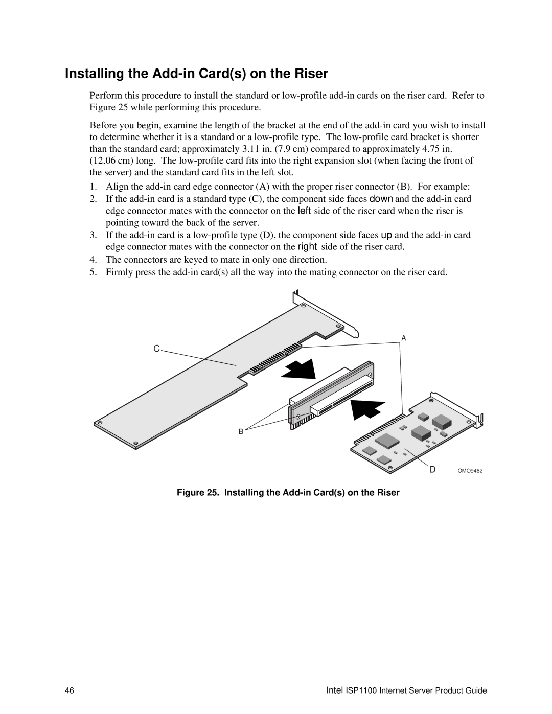
Installing the Add-in Card(s) on the Riser
Perform this procedure to install the standard or
Before you begin, examine the length of the bracket at the end of the
(12.06 cm) long. The
1.Align the
2.If the
3.If the
4.The connectors are keyed to mate in only one direction.
5.Firmly press the
A
C
B
D OMO9462
Figure 25. Installing the Add-in Card(s) on the Riser
46 | Intel ISP1100 Internet Server Product Guide |