MPCMM0002
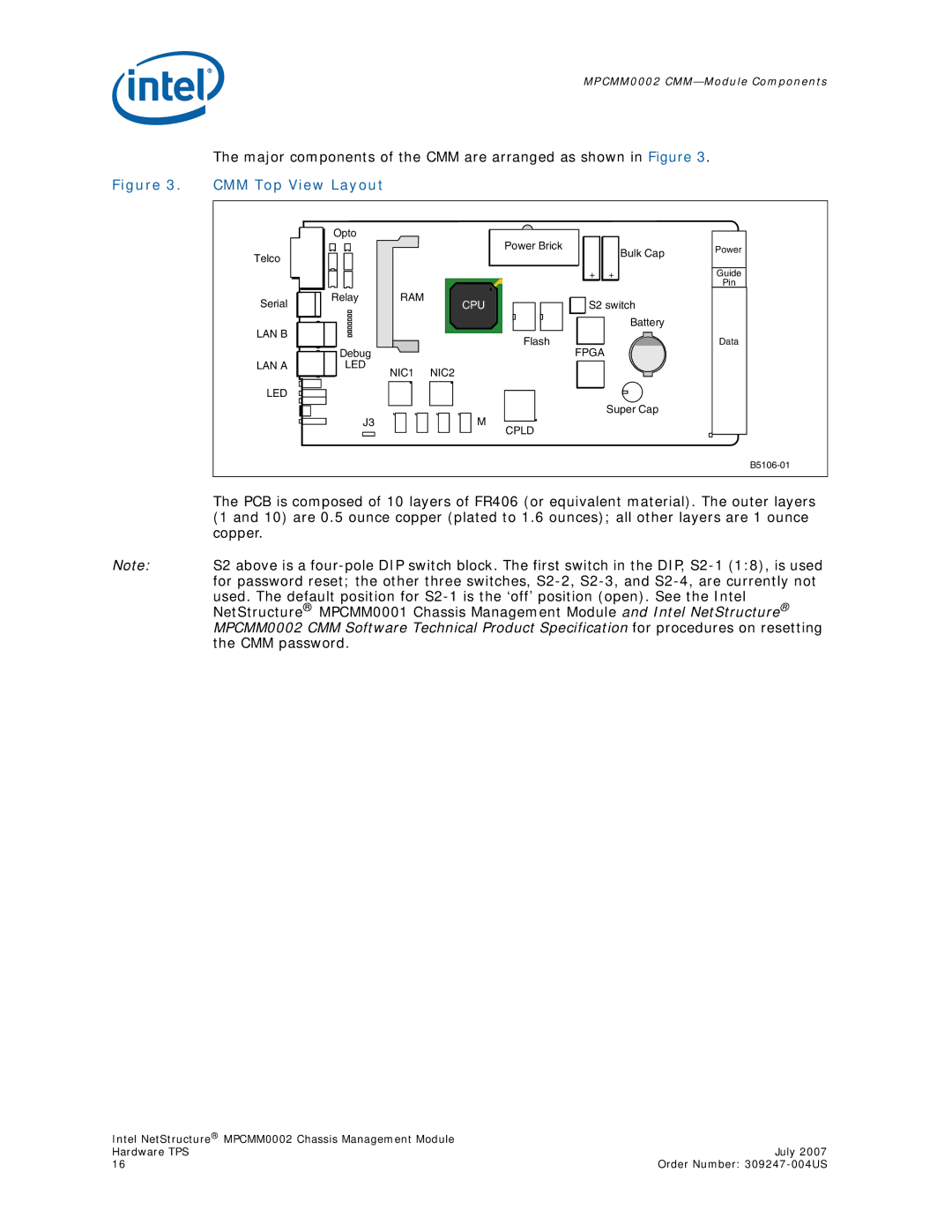
The major components of the CMM are arranged as shown in Figure 3.
Figure 3. CMM Top View Layout
Telco
Serial
LAN B
Opto
RelayRAM
| Power Brick | Bulk Cap |
|
| |
| + | + |
CPU | S2 switch | |
|
| Battery |
| Flash |
|
Power |
Guide |
Pin |
Data
LAN A
LED
Debug | FPGA |
LED | NIC2 |
NIC1 | |
| Super Cap |
J3 | M |
| CPLD |
The PCB is composed of 10 layers of FR406 (or equivalent material). The outer layers (1 and 10) are 0.5 ounce copper (plated to 1.6 ounces); all other layers are 1 ounce copper.
Note: S2 above is a
Intel NetStructure® MPCMM0002 Chassis Management Module |
|
Hardware TPS | July 2007 |
16 | Order Number: |