Front
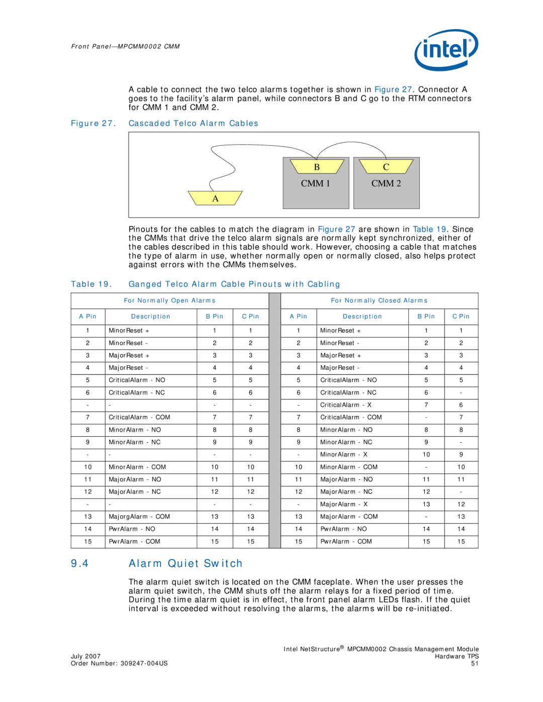
A cable to connect the two telco alarms together is shown in Figure 27. Connector A goes to the facility’s alarm panel, while connectors B and C go to the RTM connectors for CMM 1 and CMM 2.
Figure 27. Cascaded Telco Alarm Cables
A
B |
CMM 1 |
C |
CMM 2 |
Pinouts for the cables to match the diagram in Figure 27 are shown in Table 19. Since the CMMs that drive the telco alarm signals are normally kept synchronized, either of the cables described in this table should work. However, choosing a cable that matches the type of alarm in use, whether normally open or normally closed, also helps protect against errors with the CMMs themselves.
Table 19. | Ganged Telco Alarm Cable Pinouts with Cabling |
|
| ||||||
|
|
|
|
|
|
|
|
|
|
|
| For Normally Open Alarms |
|
|
| For Normally Closed Alarms |
| ||
|
|
|
|
|
|
|
|
|
|
A Pin |
| Description | B Pin | C Pin |
| A Pin | Description | B Pin | C Pin |
|
|
|
|
|
|
|
|
| |
1 | MinorReset + | 1 | 1 |
| 1 | MinorReset + | 1 | 1 | |
|
|
|
|
|
|
|
|
| |
2 | MinorReset - | 2 | 2 |
| 2 | MinorReset - | 2 | 2 | |
|
|
|
|
|
|
|
|
| |
3 | MajorReset + | 3 | 3 |
| 3 | MajorReset + | 3 | 3 | |
|
|
|
|
|
|
|
|
| |
4 | MajorReset - | 4 | 4 |
| 4 | MajorReset - | 4 | 4 | |
|
|
|
|
|
|
|
|
| |
5 | CriticalAlarm - NO | 5 | 5 |
| 5 | CriticalAlarm - NO | 5 | 5 | |
|
|
|
|
|
|
|
|
| |
6 | CriticalAlarm - NC | 6 | 6 |
| 6 | CriticalAlarm - NC | 6 | - | |
|
|
|
|
|
|
|
|
|
|
- | - |
| - | - |
| - | CriticalAlarm - X | 7 | 6 |
|
|
|
|
|
|
|
|
| |
7 | CriticalAlarm - COM | 7 | 7 |
| 7 | CriticalAlarm - COM | - | 7 | |
|
|
|
|
|
|
|
|
| |
8 | MinorAlarm - NO | 8 | 8 |
| 8 | MinorAlarm - NO | 8 | 8 | |
|
|
|
|
|
|
|
|
| |
9 | MinorAlarm - NC | 9 | 9 |
| 9 | MinorAlarm - NC | 9 | - | |
|
|
|
|
|
|
|
|
|
|
- | - |
| - | - |
| - | MinorAlarm - X | 10 | 9 |
|
|
|
|
|
|
|
|
| |
10 | MinorAlarm - COM | 10 | 10 |
| 10 | MinorAlarm - COM | - | 10 | |
|
|
|
|
|
|
|
|
| |
11 | MajorAlarm - NO | 11 | 11 |
| 11 | MajorAlarm - NO | 11 | 11 | |
|
|
|
|
|
|
|
|
| |
12 | MajorAlarm - NC | 12 | 12 |
| 12 | MajorAlarm - NC | 12 | - | |
|
|
|
|
|
|
|
|
|
|
- | - |
| - | - |
| - | MajorAlarm - X | 13 | 12 |
|
|
|
|
|
|
|
|
| |
13 | MajorgAlarm - COM | 13 | 13 |
| 13 | MajorAlarm - COM | - | 13 | |
|
|
|
|
|
|
|
|
| |
14 | PwrAlarm - NO | 14 | 14 |
| 14 | PwrAlarm - NO | 14 | 14 | |
|
|
|
|
|
|
|
|
| |
15 | PwrAlarm - COM | 15 | 15 |
| 15 | PwrAlarm - COM | 15 | 15 | |
|
|
|
|
|
|
|
|
|
|
9.4Alarm Quiet Switch
The alarm quiet switch is located on the CMM faceplate. When the user presses the alarm quiet switch, the CMM shuts off the alarm relays for a fixed period of time. During the time alarm quiet is in effect, the front panel alarm LEDs flash. If the quiet interval is exceeded without resolving the alarms, the alarms will be
| Intel NetStructure® MPCMM0002 Chassis Management Module |
July 2007 | Hardware TPS |
Order Number: | 51 |