Rear Connections—MPCMM0002 CMM
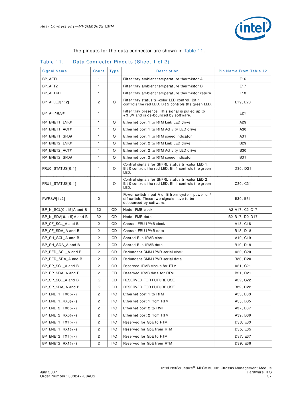
The pinouts for the data connector are shown in Table 11.
Table 11. | Data Connector Pinouts (Sheet 1 of 2) |
| |||
|
|
|
|
|
|
Signal Name |
| Count | Type | Description | Pin Name From Table 12 |
|
|
|
|
|
|
BP_AFT1 |
| 1 | I | Filter tray ambient temperature thermistor A | E16 |
|
|
|
|
|
|
BP_AFT2 |
| 1 | I | Filter tray ambient temperature thermistor B | E17 |
|
|
|
|
|
|
BP_AFTREF |
| 1 | I | Filter tray ambient temperature thermistor return | E18 |
|
|
|
|
|
|
BP_AFLED[1:2] |
| 2 | O | Filter tray status | E19, E20 |
| controls the red LED. Bit 2 controls the green LED. | ||||
|
|
|
|
| |
|
|
|
|
|
|
BP_AFPRES# |
| 1 | I | Filter tray presence. This signal is pulled up to | E21 |
| +3.3V and is | ||||
|
|
|
|
| |
|
|
|
|
|
|
RP_ENET1_LNK# |
| 1 | O | Ethernet port 1 to RTM Link LED drive | A29 |
|
|
|
|
|
|
RP_ENET1_ACT# |
| 1 | O | Ethernet port 1 to RTM Activity LED drive | A30 |
|
|
|
|
|
|
RP_ENET1_SPD# |
| 1 | O | Ethernet port 1 to RTM speed indicator | A31 |
|
|
|
|
|
|
RP_ENET2_LNK# |
| 1 | O | Ethernet port 2 to RTM Link LED drive | B29 |
|
|
|
|
|
|
RP_ENET2_ACT# |
| 1 | O | Ethernet port 2 to RTM Activity LED drive | B30 |
|
|
|
|
|
|
RP_ENET2_SPD# |
| 1 | O | Ethernet port 2 to RTM speed indicator | B31 |
|
|
|
|
|
|
|
|
|
| Control signals for ShFRU status |
|
FRU0_STATUS[0:1] | 1 | O | Bit 0 controls the red LED. Bit 1 controls the green | D30, D31 | |
|
|
|
| LED. |
|
|
|
|
|
|
|
|
|
|
| Control signals for ShFRU status |
|
FRU1_STATUS[0:1] | 1 | O | Bit 0 controls the red LED. Bit 1 controls the green | C30, C31 | |
|
|
|
| LED. |
|
|
|
|
|
|
|
|
|
|
| Power switch input A or B from system power on/ |
|
PWRSW[1:2] |
| 2 | I | off switch. These two signals have to be | E30, E31 |
|
|
|
| debounced by software. |
|
|
|
|
|
| |
BP_N_SCL[0..15]A and B | 32 | OD | Node IPMB clock | ||
|
|
|
|
| |
BP_N_SDA[0..15]A and B | 32 | OD | Node IPMB data | ||
|
|
|
|
| |
BP_CF_SCL_A and B | 2 | OD | Chassis FRU IPMB clock | A18, C18 | |
|
|
|
|
| |
BP_CF_SDA_A and B | 2 | OD | Chassis FRU IPMB data | B18, D18 | |
|
|
|
|
| |
BP_SH_SCL_A and B | 2 | OD | Shared Bus IPMB clock | A19, C19 | |
|
|
|
|
| |
BP_SH_SDA_A and B | 2 | OD | Shared Bus IPMB data | B19, D19 | |
|
|
|
|
| |
BP_RED_SCL_A and B | 2 | OD | Redundant CMM IPMB serial clock | A20, C20 | |
|
|
|
|
| |
BP_RED_SDA_A and B | 2 | OD | Redundant CMM IPMB serial data | B20, D20 | |
|
|
|
|
| |
BP_RP_SCL_A and B | 2 | OD | Reserved IPMB clocks for RTM | A21, C21 | |
|
|
|
|
| |
BP_RP_SDA_A and B | 2 | OD | Reserved IPMB data for RTM | B21, D21 | |
|
|
|
|
| |
BP_SP_SCL_A and B | 2 | OD | RESERVED FOR FUTURE USE | A22, C22 | |
|
|
|
|
| |
BP_SP_SDA_A and B | 2 | OD | RESERVED FOR FUTURE USE | B22, D22 | |
|
|
|
|
| |
2 | I/O | Ethernet port 1 to RTM | A33, B33 | ||
|
|
|
|
| |
2 | I/O | Ethernet port 1 from RTM | A35, B35 | ||
|
|
|
|
| |
2 | I/O | Ethernet port 2 to RMT | A37, B37 | ||
|
|
|
|
| |
2 | I/O | Ethernet port 2 from RTM | A39, B39 | ||
|
|
|
|
| |
2 | I/O | Reserved for GbE to RTM | D33, E33 | ||
|
|
|
|
| |
2 | I/O | Reserved for GbE from RTM | D35, E35 | ||
|
|
|
|
| |
2 | I/O | Reserved for GbE to RTM | D37, E37 | ||
|
|
|
|
| |
2 | I/O | Reserved for GbE from RTM | D39, E39 | ||
|
|
|
|
|
|
| Intel NetStructure® MPCMM0002 Chassis Management Module |
July 2007 | Hardware TPS |
Order Number: | 37 |
