MPCMM0002 CMM—Front Panel
If the alarm quiet switch is held in for more than five seconds, the processor on the CMM is reset. This is functionally equivalent to ejecting and
9.5LEDs
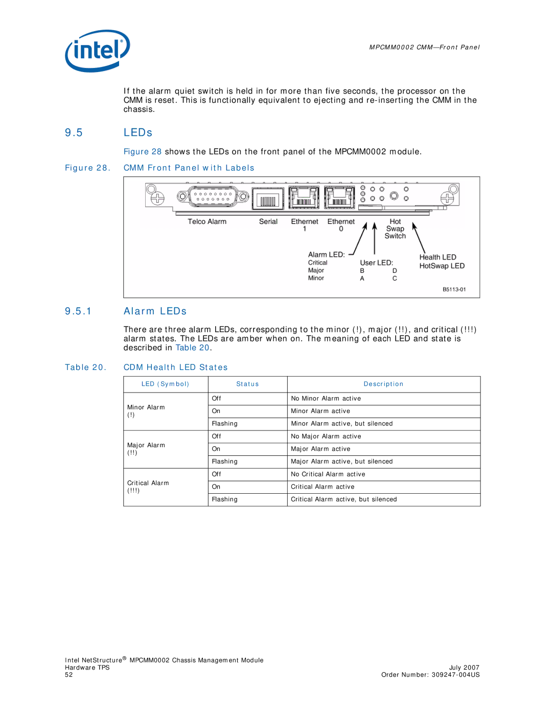
Figure 28 shows the LEDs on the front panel of the MPCMM0002 module.
Figure 28. CMM Front Panel with Labels
9.5.1Alarm LEDs
There are three alarm LEDs, corresponding to the minor (!), major (!!), and critical (!!!) alarm states. The LEDs are amber when on. The meaning of each LED and state is described in Table 20.
Table 20. | CDM Health LED States |
| |
|
|
|
|
| LED (Symbol) | Status | Description |
|
|
|
|
|
| Off | No Minor Alarm active |
| Minor Alarm |
|
|
| On | Minor Alarm active | |
| (!) | ||
|
|
| |
|
| Flashing | Minor Alarm active, but silenced |
|
|
|
|
|
| Off | No Major Alarm active |
| Major Alarm |
|
|
| On | Major Alarm active | |
| (!!) | ||
|
|
| |
|
| Flashing | Major Alarm active, but silenced |
|
|
|
|
|
| Off | No Critical Alarm active |
| Critical Alarm |
|
|
| On | Critical Alarm active | |
| (!!!) | ||
|
|
| |
|
| Flashing | Critical Alarm active, but silenced |
|
|
|
|
Intel NetStructure® MPCMM0002 Chassis Management Module |
|
Hardware TPS | July 2007 |
52 | Order Number: |