Manuals
/
Brands
/
Musical Instruments & Equipment
/
Drums
/
Intel
/
Musical Instruments & Equipment
/
Drums
Intel
MPCMM0002
7.1.2 CMM Data Connector
1
35
93
93
Download
93 pages, 1.15 Mb
MPCMM0002 CMM—Re
ar Connections
Intel NetStructure
®
MPCMM0002 Chassis Management Module
Hardware TPS
July2007
36
Order Number: 309247-004US
7.1.2
CMM Data Connector
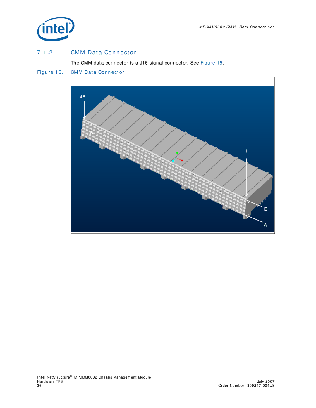
The CMM data connector is a J16 signal connector. See
Figure15
.
Figure 15.
CMM Data Connector
A
E
A
48
1
Contents
Main
Page
Contents
Page
Figures
Tables
Page
Revision History
1.0 Document Organization
1.1 Acronyms and Terms
The following special acronyms and terms are used in this specification: Table 1. Acronyms and Terms
2.0 Introduction
2.1 Architecture Specification
2.2 User Documentation
2.3 Product Definition
Page
3.0 Getting Started
3.1 Installing the CMM
3.1.1 Quick Start
4.0 Module Components
4.1 Block Diagram
FPGA 1
FPGA 2
Page
4.2 Intel 80321 Processor
Figure 4. Intel 80321 Processor Internal Block Diagram
Table 2. Processor Features (Sheet 1 of 2)
Table 2. Processor Features (Sheet 2 of 2)
4.3 Memory
4.4 Ethernet
4.5 Serial Port UARTs
4.6 FPGA
4.7 Redundancy and Hot Swap CPLD
4.8 Watchdog Timer
4.9 Real-Time Clock
4.10 ADM1026 Controller
4.11 Hot Swap Controller
4.12 Ride-Through Support
4.13 IPMB Isolation Logic
4.13.1 Dual Star IPMB Isolation
CMM 1
CMM 2
Figure 6. Dual Bus IPMB Isolation
FPGA 2
5.0 Mechanical Information
5.1 Dimensions
Page
5.2 Front Panel Hardware
5.3 Rear Connector Placement
5.3.1 MPCMM0002 CMM Rear Connectors
5.3.2 Coplanar Mating Connectors
5.3.3 Vertical Mating Connectors
5.4 ESD Discharge Strip
6.0 Backplane Considerations
6.1 IPMB Routing
6.2 CMM Power
6.2.1 DC Power Input
6.2.2 CDM Power
6.2.3 Filter Tray
CDM 1 CDM 2
6.2.4 Power Switch
6.2.5 Ethernet Routing
CMM 1
LAN A LAN B
CMM 2
LAN A LAN B
Ethernet Fabric A
7.0 Rear Connections
7.1 CMM Connector Pinouts
7.1.1 CMM Power Connector
The pinout of each CMM power connector is shown in Tabl e 6. Table 6. Power Connector Pinouts
Page
Table 10. Power Connector Header Pin Placement
Table 9. Power Connector Receptacle Pin Placement (Sheet 2 of 2)
7.1.2 CMM Data Connector
The pinouts for the data connector are shown in Tabl e 11.
Table 11. Data Connector Pinouts (Sheet 1 of 2)
Table 11. Data Connector Pinouts (Sheet 2 of 2)
Table 12. Data Connector Pinouts Matrix (Sheet 1 of 3)
Table 12. Data Connector Pinouts Matrix (Sheet 2 of 3)
Page
7.2 Guide Post
7.3 CMM Redundancy
Page
8.0 Chassis Data Modules (CDMs)
8.1 CDM Overview
8.2 CDM LED
8.3 CDM Management
8.4 CDM Power
8.5 CDM Redundancy
9.0 Front Panel
9.1 Serial Port Pinouts
Page
9.2 Ethernet Port Pinouts
9.3 Telco Alarm Connector
9.3.1 Cascading the Telco Alarm Connectors
Page
9.4 Alarm Quiet Switch
CMM 2CMM 1
B C A
9.5 LEDs
9.5.1 Alarm LEDs
9.5.2 Health LED
9.5.3 Hot Swap LED
9.5.4 User-Definable LEDs
10.0 Grounding Considerations
10.1 ESD Discharge Protection
10.2 Chassis Ground and Logic Ground
11.0 Thermals
11.1 Processor Heat Sink
11.2 Module Orientation
11.3 Module Airflow Path
Page
11.4 Airflow Requirements
11.5 Board Resistance Curve
11.6 Thermal Sensors
12.0 Management Module Specifications
12.1 Feature Summary
12.2 Dimensions and Weight
See Section 5.1, Dimensions on page 24 for more information.
12.3 Environmental Characteristics
12.4 Product Reliability Estimate
Table 25. Dimensions and Weight
12.5 Agency Certifications
13.0 Guidelines for Third Party Chassis Vendors
13.1 High Level Design
13.2 IPMB Buses
Page
Guidelines for Third Party Chassis VendorsMPCMM0002 CMM
Figure 34. Radial Bus Topology
13.3 GPIO Pins
13.3.1 Dedicated I/O Pins
13.4 Interfacing FRUs to the CMM
13.4.1 Example Configurations
13.4.1.1 Example Chassis Configuration #1
13.4.1.2 Example Chassis Configuration #2
13.4.1.3 Example Chassis Configuration #3
13.5 Intelligent FRUs
13.6 Non-Intelligent FRUs with I2C* Support
13.6.1 FRUs Based on the ADM1026
13.6.2 Two-Wire Serial Interface Based
13.7 Non-Intelligent FRUs without I2C Support
13.8 FRU Data Storage for Non-Intelligent Devices
13.9 Controllers and I/O Ports for Non-Intelligent Devices
13.10 Temperature Sensors Fronted by the CMM
13.11 Related Documents
14.0 Warranty Information
14.1 Intel NetStructure Compute Boards & Platform Products Limited Warranty
14.2 Returning a Defective Product (RMA)
14.3 For the Americas
14.3.1 For Europe, Middle East, and Africa (EMEA)
14.3.2 For Asia and Pacific (APAC)
Page
15.0 Customer Support
15.1 Customer Support
15.2 Technical Support and Return for Service Assistance
15.3 Sales Assistance
15.4 Product Code Summary
16.0 Certifications
16.1 Material Declaration Data Sheet
MPCMM0002 CMMCertifications
Material Declaration Data Sheet
17.0 Agency Information
17.1 North America (FCC Class A)
17.2 Canada Industry Canada (ICES-003 Class A) (English and French-translated below)
17.3 Safety Instructions (English and French-translated below)
17.3.1 English
17.4 Taiwan Class A Warning Statement
17.3.2 French
Page
18.0 Safety Warnings
18.1 Mesures de Scurit
Page
18.2 Sicherheitshinweise
Page
18.3 Norme di Sicurezza
Page
18.4 Instrucciones de Seguridad
Page
18.5 Chinese Safety Warning