MPCMM0002 CMM—Front Panel
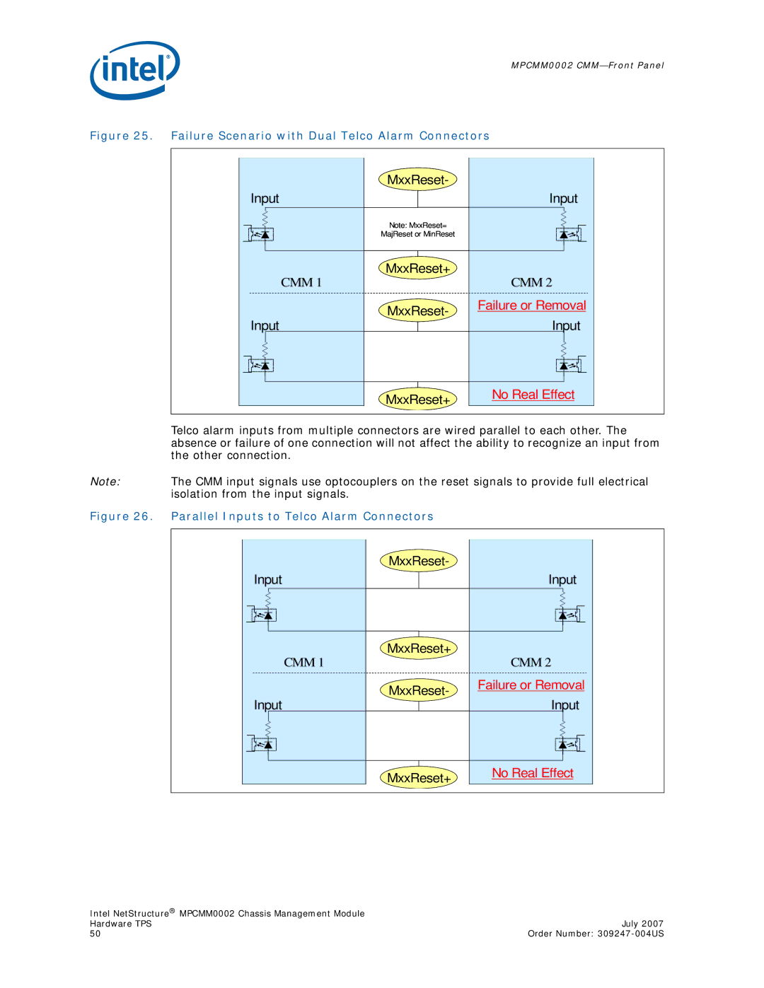
Figure 25. Failure Scenario with Dual Telco Alarm Connectors
| MxxReset- |
| |
Input |
| Input | |
| Note: MxxReset= |
| |
| MajReset or MinReset |
| |
CMM 1 | MxxReset+ | CMM 2 | |
| |||
| MxxReset- | Failure or Removal | |
Input | Input | ||
| |||
| MxxReset+ | No Real Effect | |
|
|
Telco alarm inputs from multiple connectors are wired parallel to each other. The absence or failure of one connection will not affect the ability to recognize an input from the other connection.
Note: The CMM input signals use optocouplers on the reset signals to provide full electrical isolation from the input signals.
Figure 26. Parallel Inputs to Telco Alarm Connectors
| MxxReset- |
| |
Input |
| Input | |
CMM 1 | MxxReset+ | CMM 2 | |
| |||
| MxxReset- | Failure or Removal | |
Input | Input | ||
| |||
| MxxReset+ | No Real Effect | |
|
|
Intel NetStructure® MPCMM0002 Chassis Management Module |
|
Hardware TPS | July 2007 |
50 | Order Number: |