MPCMM0002
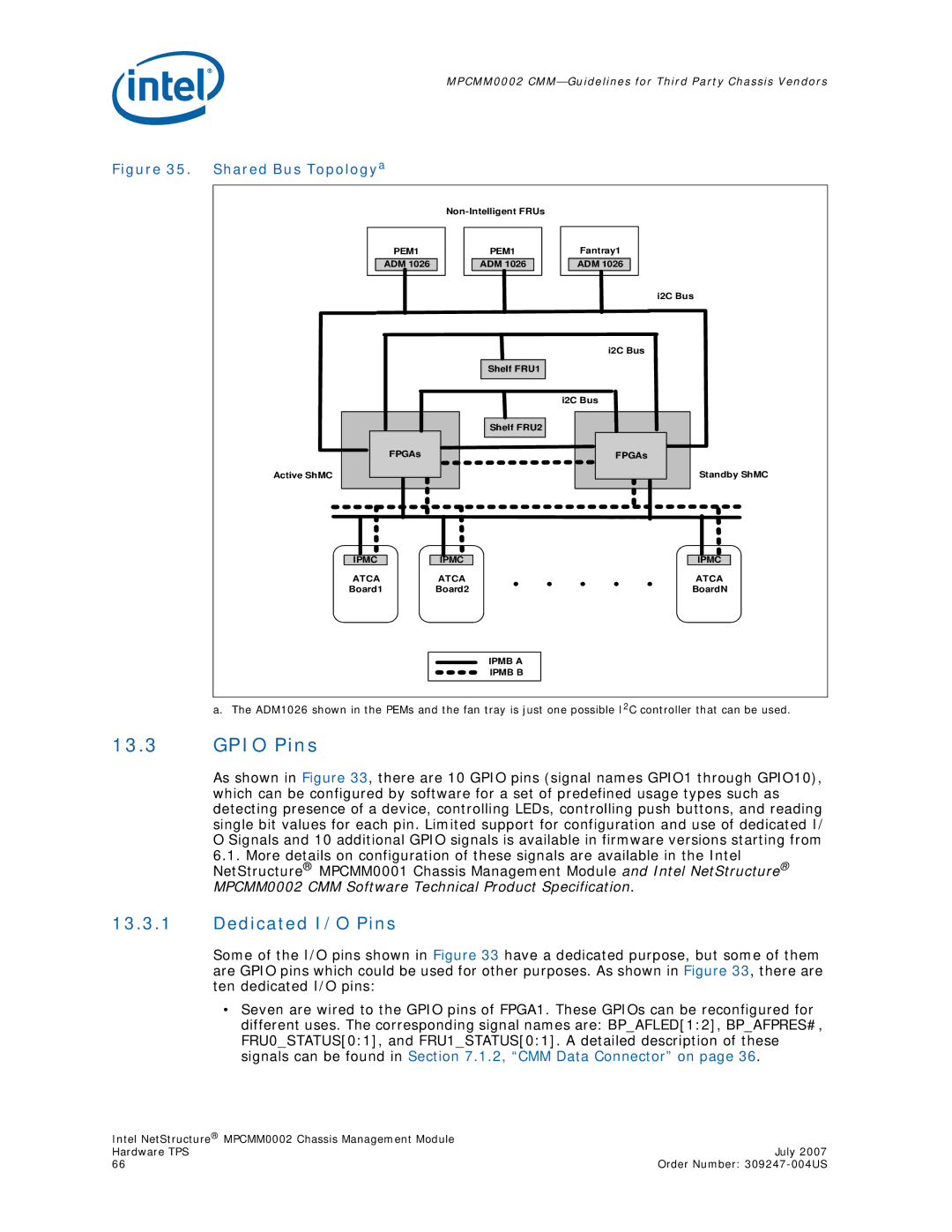
Figure 35. Shared Bus Topologya
PEM1
ADM 1026
PEM1
ADM 1026
Shelf FRU1
Shelf FRU2
Fantray1
ADM 1026
i2C Bus
i2C Bus
i2C Bus
Active ShMC
FPGAs
FPGAs
Standby ShMC
IPMC
ATCA Board1
IPMC
ATCA
Board2
IPMB A
IPMB B
IPMC
ATCA BoardN
a. The ADM1026 shown in the PEMs and the fan tray is just one possible I2C controller that can be used.
13.3GPIO Pins
As shown in Figure 33, there are 10 GPIO pins (signal names GPIO1 through GPIO10), which can be configured by software for a set of predefined usage types such as detecting presence of a device, controlling LEDs, controlling push buttons, and reading single bit values for each pin. Limited support for configuration and use of dedicated I/ O Signals and 10 additional GPIO signals is available in firmware versions starting from
6.1. More details on configuration of these signals are available in the Intel NetStructure® MPCMM0001 Chassis Management Module and Intel NetStructure® MPCMM0002 CMM Software Technical Product Specification.
13.3.1Dedicated I/O Pins
Some of the I/O pins shown in Figure 33 have a dedicated purpose, but some of them are GPIO pins which could be used for other purposes. As shown in Figure 33, there are ten dedicated I/O pins:
•Seven are wired to the GPIO pins of FPGA1. These GPIOs can be reconfigured for different uses. The corresponding signal names are: BP_AFLED[1:2], BP_AFPRES#, FRU0_STATUS[0:1], and FRU1_STATUS[0:1]. A detailed description of these signals can be found in Section 7.1.2, “CMM Data Connector” on page 36.
Intel NetStructure® MPCMM0002 Chassis Management Module |
|
Hardware TPS | July 2007 |
66 | Order Number: |