Front
Table 15. RTM Serial Port Pinout
Pin | Signal | Description |
|
|
|
6 | RXD | Receive Data |
|
|
|
7 | DSR | Data Set Ready |
|
|
|
8 | CTS | Clear To Send |
|
|
|
9.2Ethernet Port Pinouts
The CMM faceplate has two Fast Ethernet ports. The two Ethernet channels can be switched via software to the backplane connections or the RTM connections, but the default state is for the Ethernet ports to come out the front of the CMM. The connections are
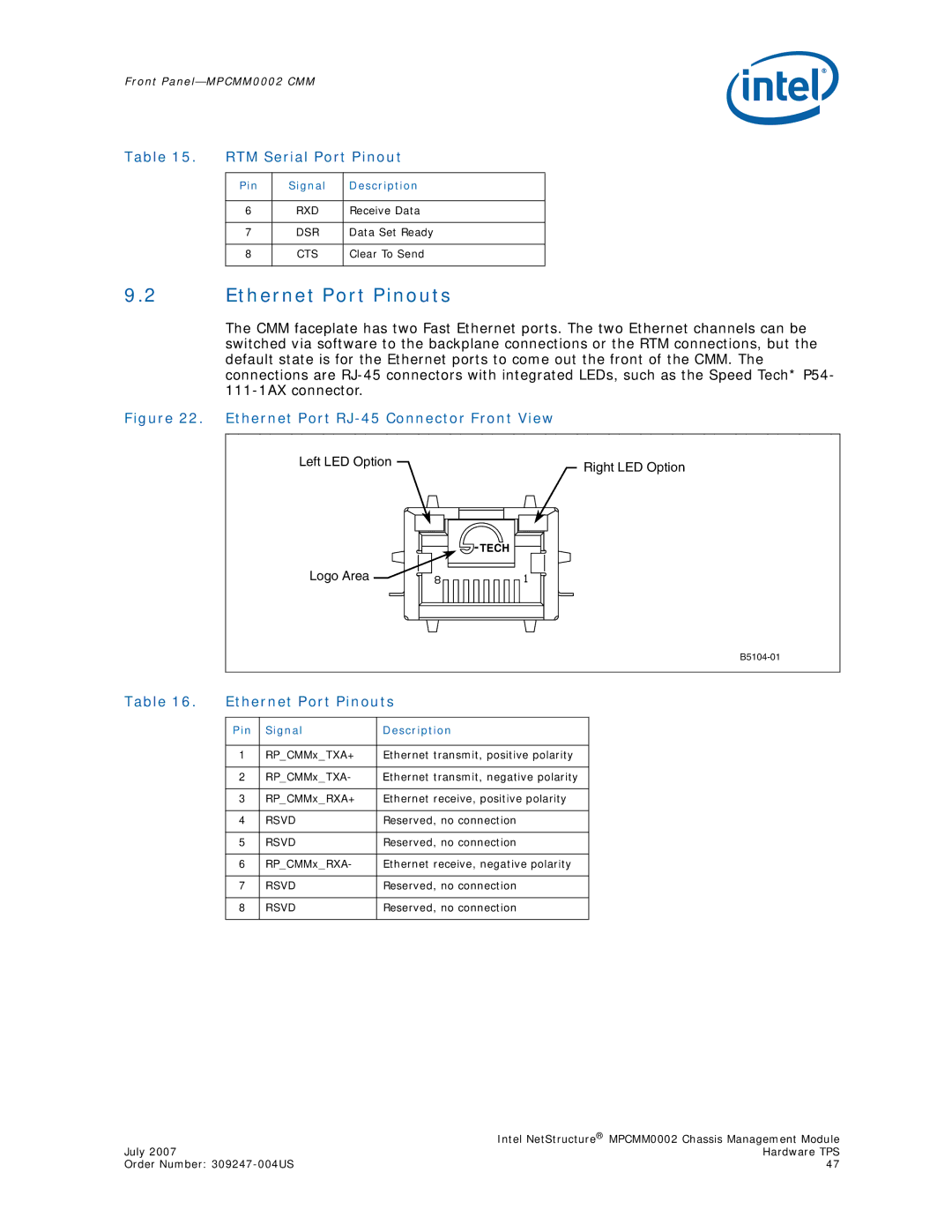
Figure 22. Ethernet Port RJ-45 Connector Front View
Left LED Option | Right LED Option |
|
Logo Area![]()
TECH
Table 16. | Ethernet Port Pinouts | ||
|
|
|
|
| Pin | Signal | Description |
|
|
|
|
| 1 | RP_CMMx_TXA+ | Ethernet transmit, positive polarity |
|
|
|
|
| 2 | RP_CMMx_TXA- | Ethernet transmit, negative polarity |
|
|
|
|
| 3 | RP_CMMx_RXA+ | Ethernet receive, positive polarity |
|
|
|
|
| 4 | RSVD | Reserved, no connection |
|
|
|
|
| 5 | RSVD | Reserved, no connection |
|
|
|
|
| 6 | RP_CMMx_RXA- | Ethernet receive, negative polarity |
|
|
|
|
| 7 | RSVD | Reserved, no connection |
|
|
|
|
| 8 | RSVD | Reserved, no connection |
|
|
|
|
| Intel NetStructure® MPCMM0002 Chassis Management Module |
July 2007 | Hardware TPS |
Order Number: | 47 |