Dell PowerEdge R815
February
Contents
Uefi Boot Settings Screen
Processor Settings Screen
Using the System Password Using the Setup Password Contents
Other Information You May Need
Removing an Optical Drive Installing an Optical Drive
Installing a Hard Drive Into a Hard-Drive
Installing a Power Supply Contents
General Memory Module Installation
Removing the Cooling Shroud Installing the Cooling Shroud
Installing Memory Modules Removing Memory Modules
Installing the Cooling Fan Assembly
Replacing the System Battery 132
Installing the Integrated Storage
Removing the Integrated Storage
116
Troubleshooting a Wet System 154
Installing the Control Panel
Troubleshooting System Memory 159 Contents
Removing the Control Panel
175
171
181
Disabling a Forgotten Password 183
185
Accessing System Features During Startup
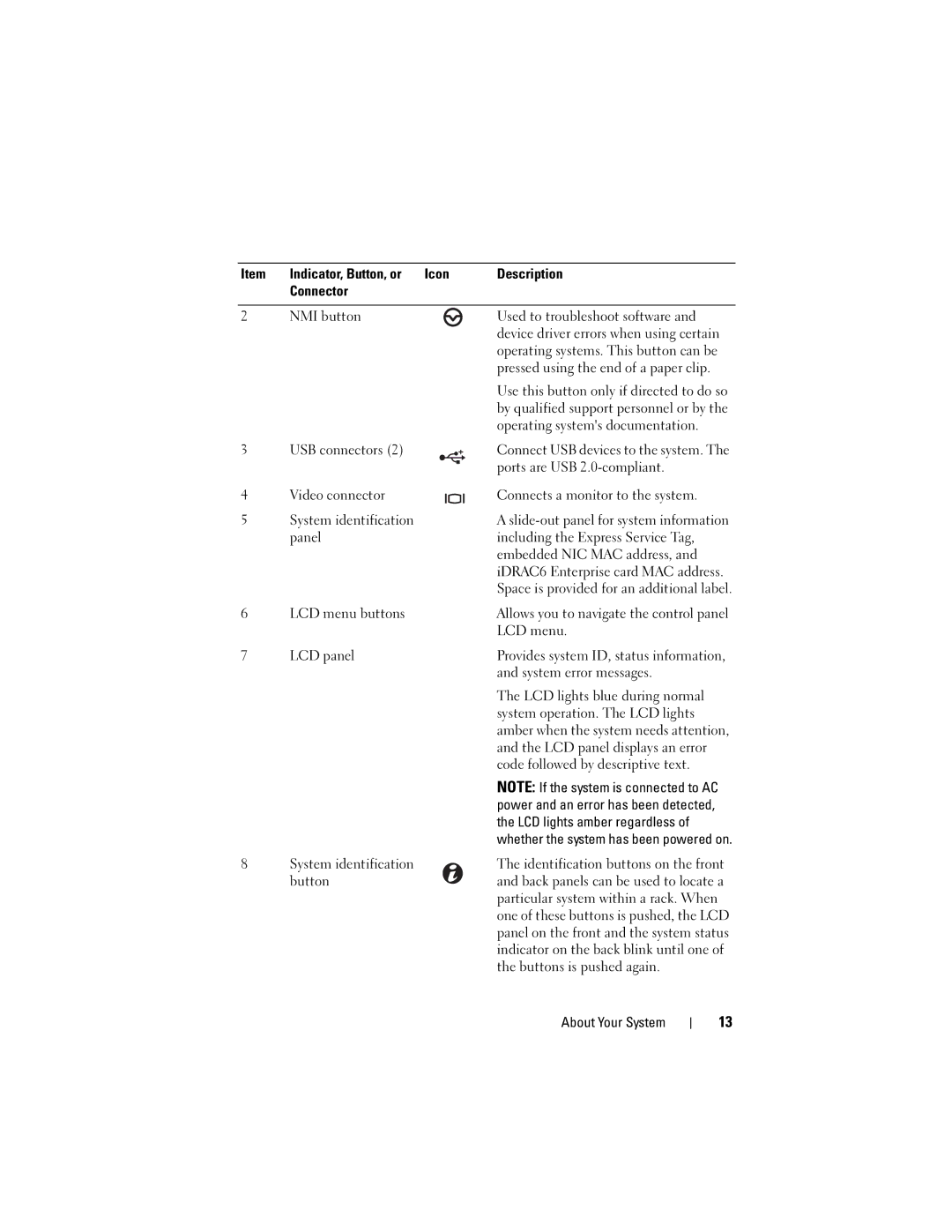
Front-Panel Features and Indicators
System error messages
USB connectors
LCD panel displays an error
Operating systems documentation
LCD Panel Features About Your System
LCD Panel Features
Buttons Description Left
Home Screen
Setup Menu
View Menu
Hard-Drive Indicator Patterns
Condition
Back-Panel Features and Indicators
Time
Height bracket
Ethernet connectors
PCIe slot PCI Express Generation 2 x8 link
Cable management arm
NIC Indicator Codes
Guidelines for Connecting External Devices
Link indicator
VFlash media slot
Power Indicator Codes
Viewing Status Messages
LCD Status Messages
Removing LCD Status Messages
Check Battery E1211 RAID
Battery
Check Battery
Power
Regulator #
E122D Memory
Failed
Reseat DIMMs
Or Bios
Configuration
Error. Power Cycle AC
E1414 CPU # temp
Check error
Error. Power
Power cycle
E1610 Power Supply
Power error
E1620 Power Supply
E1624 Lost power
E1629 Power
E1710 Channel
Error on Bus
Review
Clear SEL
E1714 Unknown
Error. Review
E1715 Fatal I/O
E1716 Chipset Ierr
Reconfigure
Fault. Review
E171F PCIe fatal
E1810 Hard drive ##
SD Module
E1813 Internal Dual
Card #
Failed. Check
But unusable Check DIMMs E2013 Bios unable
Configured
E2010 Memory not
Inspect
Timer error
E2017 Timer refresh
E2019 Parity error. Parity error
E2018 Programmable
Initialization configuration
Configuration failure
E201D Shutdown test
E201E Post memory
Disabled on
Error on Dimm
E2110 Multibit
##. Reseat
W1100
W1630 Power supply
Temp
Fans W1102 Mem Voltage
System Messages
Alert! Power
Disabled! Memory
Memory disabled
Alert! Node
Boot
Fatal error
Mode detected
Nvramclr jumper is installed on system board
CPUs with
Bootable media is
Different cache
Sizes detected
Please run Setup
Correct Connectors
Auxiliary Device
Failure. Verify
Disabled. If
Accessible USB
No boot device
Keyboard fuse has
No timer tick
No boot sector on
Interrupt PCI Bios failed
To install
Seek error
Read fault
Requested sector
Not found
Timer chip
Setup program
Will now reset
Amount
Protected mode
System Services
Operation is
Pending. Press
System reset
Error has caused
Not installed
Code update
Degraded. CPU
Performance
Memory set to
Frequencies to
Following faulty
Error caused a
Installed memory
Configuration is
Alert Messages
Diagnostics Messages
Other Information You May Need
Using the System Setup Program and Uefi Boot Manager
Choosing the System Boot Mode
Responding to Error Messages
Entering the System Setup Program
Using the System Setup Program Navigation Keys
System if any changes were made
Memory Settings Screen on
System Setup Options
Main Screen
Boot Settings
Sata Settings
Power Management
Fans, and memory modules with preconfigured or
Memory Settings Screen
Enabled default Technology Number of Cores per
Processor Settings Screen
Processor All default
Option Description 64-bit
Boot Settings Screen
Sata Settings Screen
Integrated Devices Screen
Serial Communication Screen
PCI IRQ Assignments Screen
Power Management Screen
System Security Screen
User Defined Delay Delay defined by the user
Entering the Uefi Boot Manager
Exit Screen
To 240 seconds
Uefi Boot Manager Screen
Using the Uefi Boot Manager Navigation Keys
Uefi Boot Settings Screen
System and Setup Password Features
System Utilities Screen
Using the System Password
Using the System Setup Program and Uefi Boot Manager
Using the Setup Password
Embedded System Management
Entering the iDRAC6 Configuration Utility
IDRAC6 Configuration Utility
Using the System Setup Program and Uefi Boot Manager
Recommended Tools
Installing System Components
Inside the System
Memory modules 8 to
Front Bezel Optional
Installing the Front Bezel
Removing the Front Bezel
Front bezel
Opening the System
Opening and Closing the System
Cover
Closing the System
Removing a Hard-Drive Blank
Hard Drives
Removing and Installing a Hard-Drive Blank Hard-drive blank
Installing a Hard-Drive Blank
Removing a Hard-Drive Carrier
Hard-drive carrier handle
Installing a Hard-Drive Carrier
Removing a Hard Drive From a Hard-Drive Carrier
Installing a Hard Drive Into a Hard-Drive Carrier
SAS/SATA screw hole Screws
Removing an Optical Drive
Optical Drive
Removing and Installing the Optical Drive Power/data cable
Installing an Optical Drive
Power Supplies
Release latch Installing System Components
Removing a Power Supply
Removing the Power Supply Blank
Installing a Power Supply
Installing the Power Supply Blank
Removing the Cooling Shroud
Cooling Shroud
Shroud tabs Touch points
Installing the Cooling Shroud
Front-Chassis Assembly
Cable clamp Release tabs Sata cable SAS cables
System Memory
Memory Sparing Support
General Memory Module Installation Guidelines
A1,A2,A3,A4 B1,B2, B3,B4
Memory Configurations Two Processors
A1,A2,A3,A4,A5,A6
A7,A8 B7,B8
A1,A2,A3 B1,B2,B3 C1,C2 D1,D2 C3,C4 D3,D4
Memory Configurations Four Processors
C5, C6 D5, D6 C7, C8 D7, D8
A1,A2,A3 B1,B2 C1,C2 D1,D2 B3,B4 C3,C4 D3,D4 96a
Processors 160b
Installing Memory Modules
11. Installing and Removing a Memory Module Memory module
Removing Memory Modules
Removing a Cooling Fan
Cooling Fans