Appendix D: LED Decoder
During the system boot process, BIOS executes a number of platform configuration processes, each of which is assigned a specific hex POST code number. As each configuration routine is started, BIOS will display the given POST code to the POST Code Diagnostic LEDs found on the back edge of the server board. To assist in troubleshooting a system hang during the POST process, the Diagnostic LEDs can be used to identify the last POST process to be executed.
Each POST code will be represented by a combination of colors from the four LEDs. The LEDs are capable of displaying three colors: green, red, and amber. The POST codes are divided into two nibbles, an upper nibble and a lower nibble. Each bit in the upper nibble is represented by a red LED and each bit in the lower nibble is represented by a green LED. If both bits are set in the upper and lower nibbles then both red and green LEDs are lit, resulting in an amber color. If both bits are clear, then the LED is off.
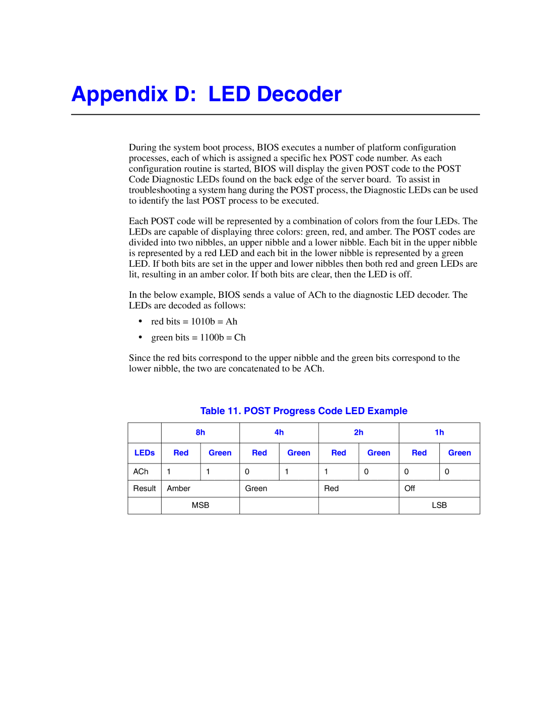
In the below example, BIOS sends a value of ACh to the diagnostic LED decoder. The LEDs are decoded as follows:
•red bits = 1010b = Ah
•green bits = 1100b = Ch
Since the red bits correspond to the upper nibble and the green bits correspond to the lower nibble, the two are concatenated to be ACh.
Table 11. POST Progress Code LED Example
|
| 8h |
| 4h |
| 2h |
| 1h | ||||
|
|
|
|
|
|
|
|
|
|
|
|
|
LEDs | Red |
| Green | Red |
| Green | Red |
| Green | Red |
| Green |
|
|
|
|
|
|
|
|
|
|
|
|
|
ACh | 1 |
| 1 | 0 |
| 1 | 1 |
| 0 | 0 |
| 0 |
|
|
|
|
|
|
|
|
|
|
|
|
|
Result | Amber |
|
| Green |
|
| Red |
|
| Off |
|
|
|
|
|
|
|
|
|
|
|
|
| ||
|
| MSB |
|
|
|
|
|
|
| LSB | ||
|
|
|
|
|
|
|
|
|
|
|
|
|