Callout | Feature | Function |
|
|
|
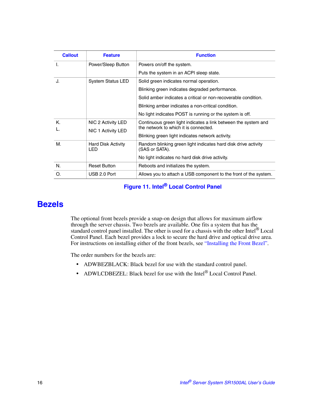
I. | Power/Sleep Button | Powers on/off the system. |
|
| Puts the system in an ACPI sleep state. |
|
|
|
J. | System Status LED | Solid green indicates normal operation. |
|
| Blinking green indicates degraded performance. |
|
| Solid amber indicates a critical or |
|
| Blinking amber indicates a |
|
| No light indicates POST is running or the system is off. |
|
|
|
K. | NIC 2 Activity LED | Continuous green light indicates a link between the system and |
L. | NIC 1 Activity LED | the network to which it is connected. |
| ||
| Blinking green light indicates network activity. | |
|
| |
|
|
|
M. | Hard Disk Activity | Random blinking green light indicates hard disk drive activity |
| LED | (SAS or SATA). |
|
| No light indicates no hard disk drive activity. |
|
|
|
N. | Reset Button | Reboots and initializes the system. |
|
|
|
O. | USB 2.0 Port | Allows you to attach a USB component to the front of the system. |
|
|
|
Figure 11. Intel® Local Control Panel
Bezels
The optional front bezels provide a
The order numbers for the bezels are:
•ADWBEZBLACK: Black bezel for use with the standard control panel.
•ADWLCDBEZEL: Black bezel for use with the Intel® Local Control Panel.
16 | Intel® Server System SR1500AL User’s Guide |