Front of Server System
Standard Control Panel
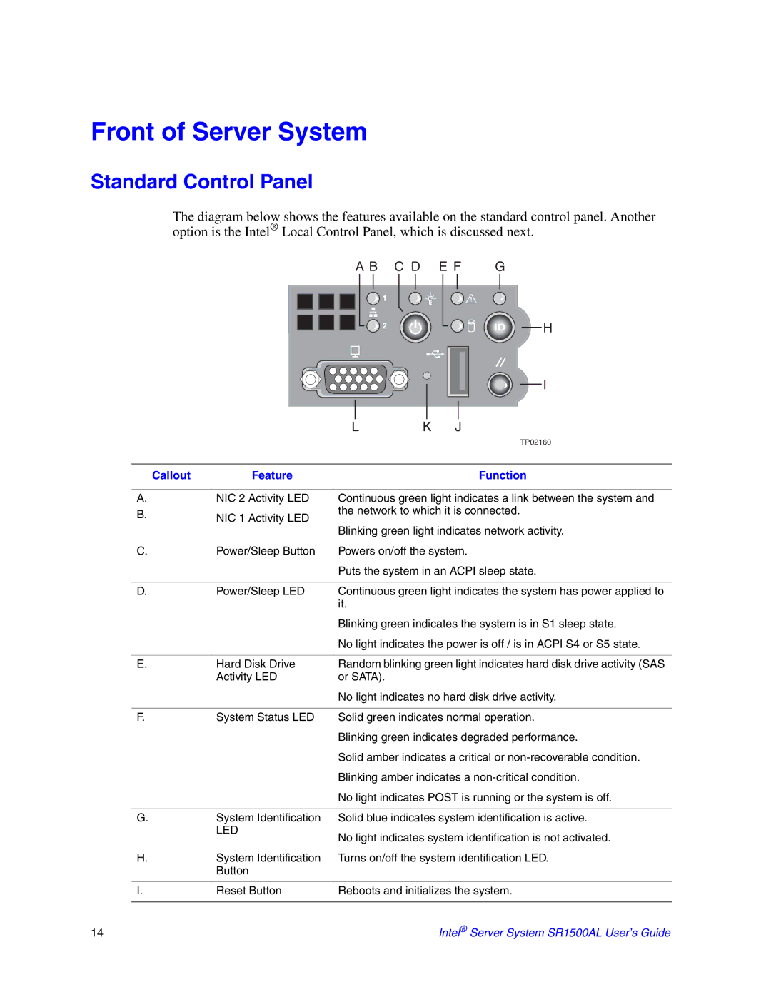
The diagram below shows the features available on the standard control panel. Another option is the Intel® Local Control Panel, which is discussed next.
A B C D E F G
|
|
|
| H |
|
|
|
| I |
|
| L | K | J |
|
|
|
| TP02160 |
Callout | Feature |
|
| Function |
A. | NIC 2 Activity LED | Continuous green light indicates a link between the system and | ||
B. | NIC 1 Activity LED | the network to which it is connected. | ||
|
|
| ||
| Blinking green light indicates network activity. | |||
|
| |||
C. | Power/Sleep Button | Powers on/off the system. | ||
|
| Puts the system in an ACPI sleep state. | ||
D. | Power/Sleep LED | Continuous green light indicates the system has power applied to | ||
|
| it. |
|
|
|
| Blinking green indicates the system is in S1 sleep state. | ||
|
| No light indicates the power is off / is in ACPI S4 or S5 state. | ||
E. | Hard Disk Drive | Random blinking green light indicates hard disk drive activity (SAS | ||
| Activity LED | or SATA). |
|
|
|
| No light indicates no hard disk drive activity. | ||
F. | System Status LED | Solid green indicates normal operation. | ||
|
| Blinking green indicates degraded performance. | ||
|
| Solid amber indicates a critical or | ||
|
| Blinking amber indicates a | ||
|
| No light indicates POST is running or the system is off. | ||
G. | System Identification | Solid blue indicates system identification is active. | ||
| LED | No light indicates system identification is not activated. | ||
|
| |||
H. | System Identification | Turns on/off the system identification LED. | ||
| Button |
|
|
|
I. | Reset Button | Reboots and initializes the system. | ||
14 | Intel® Server System SR1500AL User’s Guide |